- About 96Boards
- About Grove
- About the 96Boards Sensors Mezzanine Adapter
- About Linaro
- Table of Contents
- Included in this Kit
- 96Boards Sensors Mezzanine
- Grove Button Module (3.3V/5V)
- Grove Touch Sensor Module (3.3V/5V)
- Grove LED Socket Module (3.3V/5V)
- Grove Buzzer Module (5V only)
- Grove Rotary Angle Sensor Module (3.3V/5V)
- Grove Sound Sensor (5V only)
- Grove Light Sensor (3.3V/5V)
- Grove Servo (5V only)
- Grove Relay (3.3V/5V)
- Grove Temperature and Humidity Sensor (3.3V/5V)
- Grove RGB Backlight LCD (5V only)
- Introduction to the 96Boards Sensors Mezzanine
- Setting up the Sensors Mezzanine
- Using your Sensors Board
- Example Project - Hello World with the RGB LCD
- Example Project - Touch Sensor and Relay
- Example Project - Drive a Button and LED from the microcontroller
- Example Project - Buzzer and Light Sensor
- Example Project - Temperature and Humidity Display
- Example Project - Tweeting Doorbell
- Additional Resources
About 96Boards
96Boards is the first open specification to define a platform for the delivery of compatible, lowcost, small footprint, 32-bit and 64-bit Cortex-A boards from a range of ARM SoC vendors. Standardized expansion buses for peripheral I/O, display and cameras allow the hardware ecosystem to develop a range of compatible add-on products that will work on any 96Boards product over the lifetime of the platform.
About Grove
Grove is a system for wiring up sensor and control modules using standardized connectors and cables. It makes it easy to hook up any of the 100s of available Grove modules to a microprocessor system without a messy tangle of wires. Each module provides a single function, such as sensing temperature or driving an LCD.
http://wiki.seeedstudio.com/Grove-RTC/
About the 96Boards Sensors Mezzanine Adapter
The 96Boards Sensors Mezzanine is an add-on board for any 96Boards compliant baseboard including the HiKey from either CircuitCo or LeMaker, and the Qualcomm Dragonboard 410c. The Sensors mezzanine has connections for up to 18 digital, analog and i2c Grove modules plus an on-board Arduino compatible microcontroller and shield connector.
About Linaro
Linaro’s mission is to bring together industry and the open source community to work on key projects, deliver great tools, reduce industry wide fragmentation and redundant effort, and provide common software foundations for all.
Updates may be made to this guide over time. You can download the most recent version of this document from the sample code repository on GitHub: https://github.com/96boards/Starter_Kit_for_96Boards
Copyright (c) 2016 by Linaro, Ltd. This document is released under a Creative Commons Attribution-ShareAlike 4.0 International License.
Table of Contents
- About 96Boards
- About Grove
- About the 96Boards Sensors Mezzanine Adapter
- About Linaro
- Table of Contents
- Included in this Kit
- 96Boards Sensors Mezzanine
- Grove Button Module (3.3V/5V)
- Grove Touch Sensor Module (3.3V/5V)
- Grove LED Socket Module (3.3V/5V)
- Grove Buzzer Module (5V only)
- Grove Rotary Angle Sensor Module (3.3V/5V)
- Grove Sound Sensor (5V only)
- Grove Light Sensor (3.3V/5V)
- Grove Servo (5V only)
- Grove Relay (3.3V/5V)
- Grove Temperature and Humidity Sensor (3.3V/5V)
- Grove RGB Backlight LCD (5V only)
- Introduction to the 96Boards Sensors Mezzanine
- Setting up the Sensors Mezzanine
- Using your Sensors Board
- Example Project - Hello World with the RGB LCD
- Example Project - Touch Sensor and Relay
- Example Project - Drive a Button and LED from the microcontroller
- Example Project - Buzzer and Light Sensor
- Example Project - Temperature and Humidity Display
- Example Project - Tweeting Doorbell
- Additional Resources
Included in this Kit
96Boards Sensors Mezzanine
This is the adapter for connecting Grove modules to a 96Boards baseboard. It provides 18 Grove connectors, an Arduino compatible shield socket, and an ATMEGA328P microcontroller.

Grove Button Module (3.3V/5V)
This Grove module is a simple momentary on/off button. When pressed, it pulls the data line up to VCC to output a HIGH signal. When released, the data line drops down to output LOW.

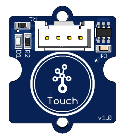
Grove Touch Sensor Module (3.3V/5V)
A simple touch sensor that behaves in a similar fashion to the button. Outputs high when touching the sensor with finger, and low otherwise.
Grove LED Socket Module (3.3V/5V)
An LED in Grove module form. Plug your favourite colour of LED into the socket, and it will glow brightly when the signal line is driven HIGH.
Grove Buzzer Module (5V only)
This module is a piezo buzzer that will emit a tone when the data line is driven HIGH, or can be made to play notes and effects by connecting it to a pulse-width modulation (PWM) output.

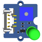
Grove Rotary Angle Sensor Module (3.3V/5V)
This Grove module outputs an analog signal between 0V and VCC based on the position of the potentiometer. It has an angular range of 300 degrees.

Grove Sound Sensor (5V only)
This is a sound sensing module with a simple microphone. It can be used to detect the volume of sound in the area. The resistance of the sensor decreases as the level of sound increases.

Grove Light Sensor (3.3V/5V)
This module detects the intensity of light shining on the sensor. The resistance of the sensor decreases as the amount of illumination increases.

Grove Servo (5V only)
The Grove servo is an actuator that is controlled by a PWM signal. The angle of the servo can be adjusted by changing the pulse width of the input PWM signal.

Grove Relay (3.3V/5V)
The Grove Relay has a normally-open SPST relay that is controlled by a single digital pin. It can be used to control power at much higher voltages that the Sensors mezzanine can handle. When the signal is LOW the relay is open. When it is driven HIGH the relay will close. Use it to control lights and equipment at up to 250V at 10 amps, but be careful when working with mains voltages.

Grove Temperature and Humidity Sensor (3.3V/5V)
This Grove module is a high accuracy temperature and humidity sensor.

Grove RGB Backlight LCD (5V only)
This is a great little display module that is easy to control. It is a 16x2 character display with an RGB backlight controller so you can set it to whatever colour you like. This module is controlled using the I2C bus.

Introduction to the 96Boards Sensors Mezzanine
The 96Boards Sensors Mezzanine board included in this kit is an IO adapter for connecting sensors, actuators and other devices to any 96Boards baseboard. The Sensors mezzanine has exactly the same footprint as a standard size 96Boards Consumer Edition baseboard and fits perfectly on top. Sensors and other devices are connected to the board via 4 pin Grove connectors or via the Arduino compatible shield socket. Additionally, the Sensors mezzanine has a USB to UART adapter for accessing the 96Boards UART console.
Features

- Low Speed Expansion connector
- USB UART console connector
- Reset and Power buttons
- 5V I2C Grove connectors
- 5V GPIO Grove connector
- 3.3V I2C Grove connectors
- 3.3V GPIO Grove connectors
- ATMEGA D3-D7 Grove connectors
- ATMEGA A0-A2 Grove connectors
- ATMEGA I2C Grove connector
- ATMEGA Arduino compatible socket
- ATMEGA Reset and Power LEDs
Setting up the Sensors Mezzanine
Step 1: Install Debian Operating System
If you haven’t already, start with installing the latest Debian image on your 96Boards baseboard. You can find instructions for installing Debian in your baseboard’s user guide.
Installing Debian on the CircuitCo or LeMaker HiKey:
/documentation/consumer/hikey/hikey620/installation/
Qualcomm Dragonboard 410C User Guide:
/documentation/consumer/dragonboard/dragonboard410c/installation/
Step 2: Attach Sensors Adapter
STOP: Before continuing, make sure to intall the 4 mounting standoffs included in the kit onto the sensor mezzanine as shown in the picture below to prevent the electrical damage to the mezzanine and/or the 96Board: 
Remove power and connect the sensors mezzanine to the baseboard. Use the 7mm standoffs included in this kit to keep the boards the correct distance apart.
WARNING: Make sure the expansion connector is correctly lined up before applying power. Connecting it incorrectly will short the +8-18V power supply rail directly to low voltage IO pins and will destroy your Sensors adapter. It may also damage your baseboard.
Step 3 Get a command prompt
Option 1: Connect a monitor, keyboard and mouse The 96Boards Debian images come with a desktop environment available for download (such as LXQt). It can be used as a normal Linux desktop computer if you attach a keyboard, mouse and monitor. Use the “Terminal” application to get a command prompt.
Option 2: Serial console The sensors board has a USB to Serial interface for connecting to the baseboard’s serial console. Use a MicroUSB cable to connect the Sensors board to your computer and use your favourite console program at 115200 baud to get a command prompt. For example, using the ‘screen’ program on a Linux machine:
$ screen /dev/ttyUSB0 115200
Or on OSX:
$ screen /dev/tty.usbserial-08-15 115200
Option 3: Secure Shell After connecting to the network (see below), you can get a command prompt with SSH:
$ ssh linaro@<ip-address-of-board>
password: <password default is "linaro">
Step 4: Connect to the network
The examples in this guide require additional software to be installed. The board needs to be connected to the Internet to download and install the required packages.
IMPORTANT: Change the password with the ‘passwd’ command before connecting to the Internet Otherwise anyone will be able to ssh into your board using the default password.
$ passwd linaro
Enter new UNIX password: <enter new password>
Retype new UNIX password: <retype new password>
To connect to a wifi network, use the status bar Network icon in the desktop or use the “nmtui” command from the console.
$ nmtui # Will give you a list of available wifi networks
Step 5: Update Debian
Make sure all of the Debian packages are up to date before installing the packages required to use the Sensors Mezzanine. From a terminal window execute the following:
$ sudo apt-get update
$ sudo apt-get dist-upgrade -u
Do you want to continue? [Y/n] y
Step 6: Install extra tool packages
To run these demos, we’ll install the Debian packages for the standard Linux development tools, the Python environment, and the Arduino toolchain. Then we’ll install the MRAA and UPM packages from source.
$ sudo apt-get install arduino-mk arduino git build-essential autoconf libtool swig3.0 python-dev cmake pkg-config libpcre3-dev
$ sudo apt-get clean
Now let’s install node and npm
sudo apt-get install curl
curl -sL https://deb.nodesource.com/setup_8.x | sudo bash -
sudo apt-get install nodejs
check to make sure installed
$ node -v
v8.9.1
$ npm -v
v5.5.1
Install I/O Libaries
For the purposes of these sample excercises, the user needs to install the following packages to build from source:
$ sudo apt-get install libsoc-dev
# Note: install libsoc prior to libmraa
$ sudo apt-get install libmraa-dev
# Note: install libmraa prior to libmupm
$ sudo apt-get install libupm-dev
There is a blog on the 96boards website entitled “How do you install 96BoardGPIO, libsoc and libmraa on a new image?” that goes into more detail on how to install them, but the below instructions should work. Also note there may be cases where it’s required to update these libraries even if they are shown as being already installed.
Step 7: Configure the software
The last step is to install some configuration files so that the development tools know which devices to uses. Fetch the 96boards-tools package and install the provided configuration files:
$ sudo adduser linaro i2c # Allow the normal user to perform i2c operations
$ git clone https://github.com/96boards/96boards-tools
$ sudo cp 96boards-tools/70-96boards-common.rules /etc/udev/rules.d/
$ cat | sudo tee /etc/profile.d/96boards-sensors.sh << EOF
export JAVA_TOOL_OPTIONS="-Dgnu.io.rxtx.SerialPorts=/dev/tty96B0"
export MONITOR_PORT=/dev/tty96B0
export PYTHONPATH="$PYTHONPATH:/usr/local/lib/python2.7/site-packages"
EOF
$ sudo cp /etc/profile.d/96boards-sensors.sh /etc/X11/Xsession.d/96boardssensors
Now reboot the system to pick up all the changes
$ sudo reboot
Step 8: Fetch the sample code for projects in this guide
$ git clone https://github.com/96boards/Starter_Kit_for_96Boards
Using your Sensors Board
The Sensor mezzanine has connectors for several different types of IO. Some connectors are directly controlled by Linux on the baseboard, while others are controlled by the ATMEGA microcontroller. This section describes how to use the each of the IO connectors.
Using Baseboard I2C
96Boards defines two I2C busses named I2C0 and I2C1, and there are 2 Grove connectors for each I2C bus. On the sensors mezzanine, I2C0 is wired for 5V devices, and I2C1 is wired for 3.3V devices. When connecting an I2C module, you should check what voltage it requires and use the appropriate connector. I2C0 and I2C1 can be directly controlled from a Linux program. The MRAA library provides functions for performing I2C transactions. The Hello World example in this guide demonstrates how to use an I2C device with Linux.
Using Baseboard GPIO
96Boards defines 12 GPIO pins labeled A through L. The Sensors board connects GPIOs A & B to the “AB” Grove connector via a 5V level shifter. It also connects GPIOs E through L to Grove connectors EF, GH, IJ and KL via a 3.3V level shifter.
WARNING: The GPIO level shifters are designed for high-speed signals but have very little current drive capacity. Some Grove modules draw more current than the level shifter can supply and causes oscillation on the line. For example, the Grove LED module does not work correctly, but the Grove relay works fine. If you have trouble with a Grove module on a GPIO line, try controlling it from the microcontroller instead.
Linux GPIOs can be directly controlled from a Linux program. The MRAA library provides functions for performing GPIO transactions. GPIOs can also be controlled directly from the shell by manipulating files in the /sys/class/gpio directory.
Using ATMEGA IO
The five blue 0.1” Arduino shield connectors (P2-P6), and the 11 Grove connectors (D3-D7, A0- A2, and AI2C) are connected to the Atmel ATMEGA328P microcontroller. These connectors are not directly accessible from a Linux program. Instead, you can program the microcontroller with software to control the connectors and communicate with a Linux program via the serial port.
The microcontroller is compatible with the Arduino UNO. It can run Arduino sketches, be programmed with the Arduino tools, and can be used with Arduino shields. Everything that works with an Arduino board will work with the Sensors board, but there are a few things to be aware of.
Releasing ATMEGA from reset The ATMEGA reset signal is wired to the serial port RTS line. Avrdude (the ATMEGA programmer) toggles the RTS signal to reset the ATMEGA at various points in the programming cycle. However, it often leaves the ATMEGA in reset after programming is complete. Reset will be released when a program (ie. terminal emulator) opens the serial device, but it can also be manually controlled by using the following stty commands:
$ stty -F /dev/tty96B0 -hupcl # Release ATMEGA from reset
$ stty -F /dev/tty96B0 hupcl # Place ATMEGA into reset
Using Command Line Tools Often the easiest way to load an Arduino sketch into the ATMEGA is to use the command line. The following example will load and run the example Blink sketch using only the command line:
$ mkdir -p sketchbook/Blink
$ cd sketchbook/Blink
$ cp /usr/share/arduino/examples/01.Basics/Blink/Blink.ino .
$ ln -s /usr/share/arduino/Arduino.mk Makefile
$ make upload reset_stty # The reset_stty target releases reset
Once you execute the above command sequence you should see the led on the sensor mezzanine blinking on and off in 1 second intervals. You can now edit Blink.ino with your text editor of choice and modify the delay(1000) command, change it to delay(500) for example, rerun the make upload reset_stty command, and the led should blink twice as fast. If this is working, you are now ready to go through the excercises!
You can also use the “make monitor” command to connect the terminal to the serial port which will also release the ATMEGA from reset. The serial connection can be used as an IO channel between Linux and sketches running on the ATMEGA.
Example Project - Hello World with the RGB LCD
This is an example of how to display text on the Grove RGB LCD module and change the color of the backlight. The example is written in C++, but could easily be implemented using Python or Java.
Step 1: Setup the Hardware
Connect the Groce RGB LCD to either of the I2C0 Grove connectors

Step 2: Write the Software
Save the following as rgb_lcd_demo.cpp in a working directory on your 96boards baseboard. This below source is also in the rgb_lcd_demo directory in this repo.
#include <string>
#include "upm/jhd1313m1.hpp"

#define I2C_BUS  0
#define RGB_WHT 0xff,0xff,0xff
#define RGB_RED 0xff,0x00,0x00
#define RGB_GRN 0x00,0xff,0x00
#define RGB_BLU 0x00,0x00,0xff
#define SLEEP_TIME 2

using namespace std;
upm::Jhd1313m1* lcd;

void display(string str1, string str2, int red, int green, int blue)
{
	lcd->clear();
	lcd->setColor(red, green, blue);
	lcd->setCursor(0,0); /* first row */
	lcd->write(str1);
	lcd->setCursor(1,2); /* second row */
	lcd->write(str2);
	sleep(SLEEP_TIME);
}

int main(int argc, char* argv[])
{
	string str1 = "96Boards!";
	string str2 = "Grove Sensors!";
	string str3 = "Linaro!";

	lcd = new upm::Jhd1313m1(I2C_BUS, 0x3e, 0x62);

	if ((argc >= 2) && (argv[1] != NULL))
		str1 = argv[1];
	if ((argc >= 3) && (argv[2] != NULL))
		str2 = argv[2];
	if ((argc >= 4) && (argv[3] != NULL))
		str3 = argv[3];

	while (true) {
		display(str1, "Red", RGB_RED);
		display(str2, "Green", RGB_GRN);
		display(str3, "Blue", RGB_BLU);
	}
	delete lcd;
	return 0;
}
Step 3: Make the Demo
Enter the following from the same directory the sample code is located.
$ g++ rgb_lcd_demo.cpp -o rgb_lcd_demo -g -Wall -lupm-i2clcd
OR
$ make
Step 4: Run the demo
$ ./rgb_lcd_demo
The LCD will show some sample messages and the backlight will cycle between red, blue and green.
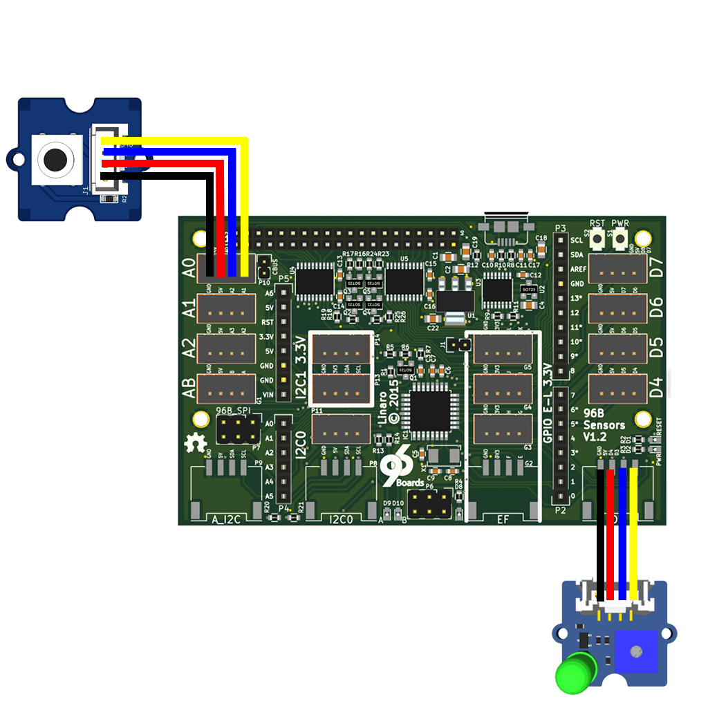
Example Project - Touch Sensor and Relay
Build a system that toggles a relay on and off when the touch sensor is tapped using Linux GPIO IO.
The pins on connectors G1 through G5 are connected to GPIO pins on the baseboard and can be directly controlled from Linux. In this project, the application reads the state of the touch sensor from GPIO-G on connector G3, and toggles the relay by driving GPIO-E on connector G2. Each time the touch sensors is tapped, the relay will toggle between on and off.
Step 1: Setup the Hardware
- Attach the relay to G2
- Attach the touch sensor to G3

Step 2: Write the Code
Save the following code also available in this repo as ./touch_switch/touch_switch.cpp:
#include <signal.h>
#include <unistd.h>
#include "mraa.hpp"

bool running = true;
bool relay_state = false;
int last_touch;

void sig_handler(int signo)
{
    if (signo == SIGINT)
        running = false;
}
int main(int argc, char* argv[])
{
    mraa::Gpio* touch_gpio = new mraa::Gpio(29);
    mraa::Gpio* relay_gpio = new mraa::Gpio(27);
    mraa::Result response;
    int touch;

    signal(SIGINT, sig_handler);

    response = touch_gpio->dir(mraa::DIR_IN);
    if (response != mraa::SUCCESS)
        return 1;
    response = relay_gpio->dir(mraa::DIR_OUT);
    if (response != mraa::SUCCESS)
        return 1;

    relay_gpio->write(relay_state);

    while (running) {
        touch = touch_gpio->read();
        if (touch == 1 && last_touch == 0) {
            relay_state = !relay_state;
            response = relay_gpio->write(relay_state);
            usleep(100000);
        }
        last_touch = touch;
    }
    delete relay_gpio;
    delete touch_gpio;
    return response;
}
Step 3: Build and Run the Demo
Build the program
$ g++ touch_switch.cpp -o touch_switch -g -Wall -lmraa
OR
make
Run the demo
$ sudo ./touch_relay # Must be run as root to access GPIOs
When the program is run, the relay will switch between on and off each time you tap the touch sensor with your finger.
Reminder: Getting an error like this?
terminate called after throwing an instance of 'std::invalid_argument'
  what():  Invalid GPIO pin specified
Aborted
It’s because you must be root to access the I/O! Don’t forget the sudo when executing the program!
Example Project - Drive a Button and LED from the microcontroller
This example shows how use the microcontroller read a button and control an LED. We will use the Arduino toolchain to program the microcontroller.
Step 1: Setup the Hardware
- Attach the Grove Button to connector A0.
- Attach the Grove LED to connector D3.
Step 2: Write the Code
Create a new directory and save the following program as “test_button_led.ino”
/*
 * Example using a button to control an LED
 * Copyright (c) 2016 Linaro Ltd.
 * SPDX-License-Identifier: BSD-2-Clause
 */
int led_pin = 3;
int button_pin = A0;

void setup()
{
    pinMode(led_pin, OUTPUT);
    pinMode(button_pin, INPUT);
}

bool last_button = false;
int led_state = 0;
void loop()
{
    bool button = digitalRead(button_pin);
    if (last_button != button)
    {
        if (button) {
            led_state = (led_state + 1) % 4;
            analogWrite(led_pin, led_state * 0x3f);
        }
        delay(100);
    }
    last_button = button;
}
Add the Arduino.mk Makefile to the same directory
$ ln -s /usr/share/arduino/Arduino.mk Makefile
Step 3: Run the Demo
Build and execute the program
$ make upload reset_stty
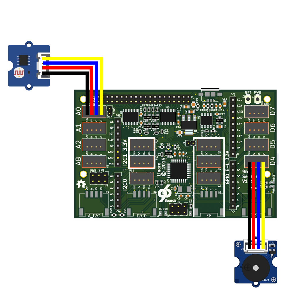
Example Project - Buzzer and Light Sensor
This example shows how to use the Grove light sensor and Grove buzzer. While the sensor detects light, the buzzer will remain silent. When dark, it will emit noise. In the example, the buzzer is connected to D4, and the light sensor to A0; but this can easily be changed by updating the variables buzzer and sensor to your prefered pins.
Step 1: Setup Hardware
- Attach the light sensor to A0
- Attach the buzzer to D4
Step 2: Write the Code
Create a new directory and save this file as “Grove_light_buzz.ino”.
//pins used for components
const int buzzer = 4;   // Arduino port pin PD4
const int sensor = A0;  // Arduino analog ping ADC0

//this is the threshold value for the light sensor
//to make the light sensor more sensitive, lower this value
int thresholdVal = 400;

void setup(){
    pinMode(sensor, INPUT); // set pin for button input
    pinMode(buzzer, OUTPUT); // set pin for buzzer output
}

void loop(){
    int sensorVal = analogRead(sensor);
    if (sensorVal < thresholdVal)
        digitalWrite(buzzer, HIGH);
    else
        digitalWrite(buzzer, LOW);
}
Step 3: Run the Demo
Add the Arduino.mk Makefile to the same directory and build and run the program from the command line.
$ ln -s /usr/share/arduino/Arduino.mk Makefile
$ make upload reset_stty
Example Project - Temperature and Humidity Display
Build a temperature and humidity display. The microcontroller is used to read the data stream from the Digital Humidity and Temperature (DHT) sensor and it passes the raw data to Linux via the serial port. The Linux program displays the temperature and humidity readings on the LCD display.
Step 1: Setup the Hardware
- Attach the RGB LCD to I2C0
- Attach the temperature and humidity sensor to A0.

Step 2: Write the Code
Save the following code as read_dht.ino
#include "DHT.h"

DHT dht(A0, DHT11);

void setup()
{
    Serial.begin(9600);
    dht.begin();
}

void loop()
{
    float h = dht.readHumidity();
    float t = dht.readTemperature();

    // check if valid, if NaN (not a number) then something went wrong!
    if (isnan(t) || isnan(h)) {
        Serial.println("Failed to read from DHT");
        return;
}

    Serial.print("Humidity: ");
    Serial.print(h);
    Serial.print(" %\t");
    Serial.print("Temperature: ");
    Serial.print(t);
    Serial.println(" *C");
    delay(2000);
}
Next save the following code as display as “humid_temp.py”
import serial, pyupm_jhd1313m1
ard = serial.Serial('/dev/tty96B0', 9600)
lcd = pyupm_jhd1313m1.Jhd1313m1(0, 0x3e, 0x62)

def showTemp(humid, temp):
    lcd.clear()
    lcd.setCursor(0, 0)
    lcd.write(humid)
    lcd.setCursor(1, 0)
    lcd.write("Temp:" + temp + " C")
    lcd.setColor(255, 180, 180)

if __name__ == '__main__':
    print("Welcome to the Humidity & Temperature reader!!!")
    try:
        while True:
            ardOut = ard.readline()
            if ardOut.find("Humidity:") != -1:
                ardHumid = ardOut.split('Temperature')[0]
                ardTemp = ardOut.split('Temperature:')[1]
                showTemp(ardHumid,ardTemp)
    except KeyboardInterrupt:
        lcd.setColor(0,0,0)
        lcd.clear()
        print("CTRL-C!! Exiting...")
Create a Makefile with the following:
include /usr/share/arduino/Arduino.mk
run: upload
    python humid_temp.py
This example also utilises an additional library to control the DHT component. You’ll need to clone the following repository, then move the DHT files into your projects directory:
$ git clone https://github.com/Seeed-Studio/Grove_Temperature_And_Humidity_Sensor.git
$ cd Grove_Temperature_And_Humidity_Sensor/
$ mv DHT.* ../
$ cd ..
Step 2: Run the Demo
To run the program, type in the terminal:
$ PYTHONPATH=$PYTHONPATH:/usr/lib/aarch64-linux-gnu/python2.7/site-packages
$ make run
And to exit, use Ctrl + C
** Potential build errors / work-arounds** 1) Build Error: ImportError: No module named pyupm_jhd1313m1 Makefile:3: recipe for target ‘run’ failed
Fix: Need to add path to PYTHONPATH PYTHONPATH=$PYTHONPATH:/usr/lib/aarch64-linux-gnu/python2.7/site-packages
2) Build Error File “/usr/lib/aarch64-linux-gnu/python2.7/site-packages/pyupm_jhd1313m1.py”, line 985 SyntaxError: Non-ASCII character ‘\xc3’ in file /usr/lib/aarch64-linux-gnu/python2.7/site-packages/pyupm_jhd1313m1.py on line 986, but no encoding declared; see http://python.org/dev/peps/pep-0263/ for details Makefile:3: recipe for target ‘run’ failed
Fix: Add # coding=utf-8 to first line of /usr/lib/aarch64-linux-gnu/python2.7/site-packages/pyupm_jhd1313m1.py and save
Example Project - Tweeting Doorbell
In this project, You’ll write an application in Python to take input from sensors and communicate on the Internet. This project creates a “tweeting” doorbell which sends a message out to twitter every time the button is pressed.
To send tweets from Python, we need to install an additional library. Use apt-get to install the “Tweepy” package:
$ sudo apt-get install python-tweepy
Step 1: Setup the Hardware
- Connect the LED module to D3
- Connect the Button module to D4
- Connect the Buzzer module to D5
- Connect the RGB LCD to I2C0

Step 2: Write the Code
This example requires some extra setup to communicate with Twitter. You will need to have a twitter account and obtain oauth details from https :// apps . twitter . com by creating an app. Put the oauth details into a file named keys.py:
consumer_key = “YourConsumerKey”
consumer_secret = “YourConsumerSecret”
access_token = “YourAccessToken”
access_token_secret = “YourAccessSecret”
Save the following code as tweeting_doorbell.ino:
const int buttonPin = 4;
const int ledPin = 3;
const int buzzerPin = 5;

void setup() {
    pinMode(buttonPin, INPUT);
    pinMode(ledPin, OUTPUT);
    pinMode(buzzerPin, OUTPUT);
    Serial.begin(115200);
    Serial.println("waiting");
}

void loop() {
    int pressed = digitalRead(buttonPin);
    if (pressed == 1) {
        digitalWrite(ledPin, HIGH);
        digitalWrite(buzzerPin, HIGH);
        Serial.println("tweet");
        delay(1000);
        digitalWrite(buzzerPin, LOW);
        digitalWrite(ledPin, LOW);
    }
}
Save the following code as tweeting_doorbell.py:
import tweepy, serial, datetime, time, keys, pyupm_jhd1313m1

auth = tweepy.OAuthHandler(keys.consumer_key,
keys.consumer_secret)
auth.set_access_token(keys.access_token,
keys.access_token_secret)

api = tweepy.API(auth)
ard = serial.Serial('/dev/tty96B0', 115200)
lcd = pyupm_jhd1313m1.Jhd1313m1(0, 0x3e, 0x62)

def tweet():
    lcd.clear()
    today = datetime.datetime.now()
    lcd.setCursor(0, 0)
    lcd.write("Ding Dong")
    lcd.setCursor(1, 0)
    lcd.write(today.strftime('%Y/%m/%d %H:%M:%S'))
    lcd.setColor(0, 255, 0)

    msg = '(Chatty Doorbell) Ding dong! Someone was at the door at %s' % \
        today.strftime('%d/%m/%Y %H:%M:%S')
    print(msg)
    api.update_status(msg)
    time.sleep(1)

    lcd.setColor(0,0,0)
    lcd.clear()

if __name__ == '__main__':
    lcd.clear()
    lcd.setColor(0, 0, 0)
    print("Welcome to the tweeting doorbell! To quit, press CTRL + C")
    try:
        while True:
            ardOut = ard.readline()
            if ardOut.find("tweet") != -1:
                tweet()
    except KeyboardInterrupt:
        print("CTRL-C!! Exiting...")
Finally, create a Makefile:
include /usr/share/arduino/Arduino.mk
run: upload
    python tweeting_doorbell.py
Step 3: Run the Demo
To run the program, type in terminal:
$ make run
Welcome to the tweeting doorbell! To quit, press CTRL + C
(Chatty Doorbell) Ding dong! Someone was at the door at 2016/02/13 00:55:08
And to exit, use CTRL + C
Additional Resources
Design files
The UART adapter board is an entirely Open Hardware, designed using KiCad, and with all of the design files provided under a BSD license. The files can be found on GitHub:
https://github.com/96boards/96boards-sensors
More Example Core
There are many of examples of how to interface with sensors in the UPM package. Look in the examples/ subdirectory of the UPM repository for examples written in C++, Java, Javascript and Python.
https://github.com/intel-iot-devkit/upm
Example from other Kits
The examples listed in this section have not been thoroughly tested and may require changes to get to work with the 96Boards Sensors Mezzanine. They are included here for reference.
Seeed Studio Grove Starter Kit for Arduino http://wiki.seeedstudio.com/Grove_Starter_Kit_v3/
Just about all of the examples in Seeed Studio’s Arduino starter kit will work with the 96Boards Sensor board. You can get the sketch demos from:
https://github.com/Seeed-Studio/Sketchbook_Starter_Kit_for_Arduino
Dexter Industries GrovePi+ Starter Kit
http://www.dexterindustries.com/grovepi
The GrovePi+ kit demonstrates how to use the I2C bus to communicate between the baseboard and the ATMEGA microcontroller. Many of the examples in the GrovePi+ kit will work on the Sensors mezzanine with only minor modifications.
Using the GrovePi+ examples with the Sensors board requires connecting the ATMEGA to the I2C0 bus. The Sensors board has two unpopulated resistor pads along the bottom edge of the board labelled R20 and R21. Use a soldering iron to put a blob of solder across the pads of R20, and another blob over the pads of R21. This will complete the I2C connection between the ATMEGA and the baseboard.
You can download the GrovePi+ example software from github:
https://github.com/DexterInd/GrovePi