- B2260 Development 96Boards Hardware User Manual
- Introduction
- What’s in the Box
- Board Overview
- System Block Diagram
- Jumpers/Switch Configurations
- Getting Started
- Component Details
- Expansion Connectors
- Power Management Overview
- Mechanical Specification
B2260 Development 96Boards Hardware User Manual
Introduction
The ST B2260 Development Board is a 96Boards compliant community board based on ST Cannes2-STiH410 platform.
The following table lists its key features:
- Processor
- ST Cannes2-STiH410 EJB: Dual ARMcortex-A9 @ 1.5 GHz
- Graphic
- ARM Mali-400 MP2 GPU @ 355 MHz, supporting:
- EGL 1.4
- OpenGL ES 2.0
- OpenGL ES CM 1.1
- OpenVG 1.0
- ARM Mali-400 MP2 GPU @ 355 MHz, supporting:
- Display
- HDMI-A output 1080p60
- Memory / Storage
- SPI NOR
- 2 x (DDR3 16-bit 500MB)
- External Storage
- Micro SD card slot
- Video
- Video Hardware/Software encoder/decoder
- Audio
- Audio Software encoder/decoder
- Outputs: USB (digital), HDMI and PCM/I2S (via Low-speed expansion connector)
- Inputs: USB (digital), PCM/I2S(via Low-speed expansion connector)
- Connectivity
- Ethernet Port Up to 1 GB
- Wi-Fi 802.11 g/n
- Bluetooth® wireless technology 4.0 LE
- One USB 2.0 micro AB (host and device mode supported)
- Two USB 2.0 (host mode only)
- I/O Interfaces
- One 40-pin Low Speed (LS) expansion connector
- 12 x GPIO, 1 x UART 4 wires, 1 x UART 2 wires, 2 x I2C, 1 x PCM/I2S, 1 x SPI, 1 x Fan Ctrl, Reset,
- One 60-pin High Speed (HS) expansion connector
- 1 x USB, 2 x I2C, 1 x SD interface
- One 40-pin Low Speed (LS) expansion connector
- User Interface
- 1 Button: Reset
- 6 LED indicators
- 4 -user controllable
- 2 -for radios (BT and WiFi activity)
- OS Support
- Linux based on Debian ; Linux based on OpenEmbedded
- Mechanical
- Dimensions: 85mm x 100mm meeting 96Boards™ Consumer Edition standard dimensions specifications.
What’s in the Box
The box contains a B2260 Development 96board, a power supply, a power supply adapter, a populated SDCard and a product instruction manual (quick start guide).


Board Overview

| Position | Description |
|---|---|
| 1 | USB Host Connector |
| 2 | Users LEDs |
| 3 | USB Host Connector |
| 4 | LED3205 is WiFi and LED3206 is Bluetooth |
| 5 | Micro USB Type AB Connector |
| 6 | HDMI Type A Port |
| 7 | Micro SD Card Socket |
| 8 | High Speed Connector |
| 9 | Low Speed Expansion Connector |
| 10 | WiFi/Bluetooth |
| 11 | Power Outlet |
| 12 | Reset Button |
| 13 | Bluetooth/WiFi Antenna |

| Position | Description |
|---|---|
| 14 | SATA connector |
| 15 | RJ45 connector |
| 16 | JTAG connector |
| 17 | ST Cannes2-STiH410 Soc |
| 18 | 2x16b 1GB LPDDR3 |
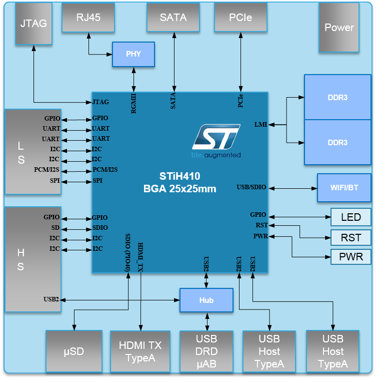
System Block Diagram
Jumpers/Switch Configurations
There is no jumper or switch to configure on the ST B2260 Development Board.
Getting Started
Prerequisites
Before power up the B2260 Development Board for the first time, following material is required:
- [B2260 Development Board](https://www.96boards.org/product/b2260/)
- Board based on the ST Cannes2-STiH410 Processor.
- Power Supply
- 96Boards specifications requires a 8V to 18V Power supply ; Recommended: SUN-1200500 by SUNUP electronics.
- a Jack adaptor ; Recommended: https://www.96boards.org/product/power/.
- USB Keyboard and Mouse
- With two USB-A connectors, all 96Boards can be equiped with a full sized AZERTY keyboard and mouse.
- Monitor and HDMI-HDMI Cable
- 96Board is equiped with a full sized HDMI connector.
- HDMI capable monitor, supported resolution up to 1080p60 is also needed.
- MicroSD card
- For booting board and for quick and easy switching between operating systems and extra storage.
- SDCard capacity is 2GB minimum.
- Optional
- Ethernet cable
- For connecting to a network without using WiFi
- 96Boards UART Adapter Board
- For connecting to PC via serial link. Useful for debugging.
- Recommended: Uart Mezzanine Product Page
- Ethernet cable
Known Limitations
To be completed if any
Starting the board for the first time
To start the board, follow these simple steps:
- 1- Connect the HDMI display cable to the B2260 HDMI connector and to the monitor,
- 2- Connect the Keyboard and the mouse to the two USB ports,
- 3- Insert the SDcard
- 4- Connect the delivered power supply (12V, 5A) to power outlet.
The board will start booting process and System will be available after X seconds.
Component Details
Processor
The Cannes2-STiH410 is a Dual core SMP ARM® Cortex™-A9 application CPU at up to 1.5 GHz delivering 7500 DMIPS, plus a quad-core ARM Mali-400 MP GPU for true 3D graphics.
Cannes2-STiH410 supports 1 Mbyte L2 cache, DDR3/DDR3L LMI running at up to 933 MHz (DDR3-1866), hardware video encode and decode.
Memory (DRAM)
The B2260 Development Board provides 1GB LPDDR3-SDRAM which is a 2 x 16bit. One 32bit width bus interfaces directly to the Cannes2-STiH410 build-in LPDDR controller. The maximum DDR clock is 1066MHz.
The B2260 Development Board provides also 16MB NOR .
Storage
96Board requirement is to support a minimum of 4GB of storage through onboard flash, USB storage, Micro SDHC or SATA interface below.
Micro SDHC
The 96Boards specification calls for a micro SDHC socket to be present on the board.
The micro SDHC is provided with boot capability.
The slot is a push-push type with a dedicated support for card detect signal.
Maximum storage is 64GB.
It meets the SD3.0 standard.
Boot ROM
The B2260 Development Board boots up from 16MB NOR.
SATA
Sata connector is provided on the B2260 Development board for connection of Sata type storage.
Support for two hard disk drivers (HDD) is provided by two embedded eSATA interfaces, allowing two HDDs to be integrated, or added using standard external SATA (eSATA) drives.
The SATA interface is compliant to Serial ATA specification for Gen3 configuration. Advanced host controller interface (AHCI) is supported.
Applications supported are:
- Internal/external HDD
- Internal/external optical drive
Networking
WiFi /Bluetooth
The 96Boards specifications calls for a WiFi (minimally 802.11g/n) and Bluetooth 4.0 LE.
The WiFi/Bluetooth controller is a Realtek RTL8723BU, highly integrated WiFi/Bluetooth single chip based on advanced CMOS process.
RTL8723BU integrates whole WiFi/Bluetooth function blocks into a chip.
Ethernet
An Ethernet connection is provided on the B2260 development Board, with an RJ45 connector.
The PHY layer technologies connected to the integrated Ethernet MAC controller supports standard Ethernet IEEE 802.3 and provides interfaces at 10 Mbps, 100 Mbps, and 1 Gbps.
GPS
The 96Boards specification calls for GPS to be present on the board.
The B2260 Development Board doesn’t include this feature.
### Graphic The graphic co-processor is an ARM Mali-400 MP2 GPU. It is compatible with the following Khronos graphics standards:
- EGL 1.4
- OpenGL ES 2.0
- OpenGL ES CM 1.1
- OpenVG 1.0
The ARM Mali-400 MP2 GPU configuration is:
- 1 Geometry Processor (GP):
- Polygon List Builder (PLB) Unit
- Vertex Shader Unit
- 2 Pixel Processors (PP):
- Rasterizer (including a Triangle setup, Polygon List Reader…) Unit
- Fragment Shader Unit
- Blending Unit
- 2 on chip tile buffers (double buffering of tile data) + Tile Writeback Unit
- 1 Level 2 cache controller (L2)
- 1 MMU for each GP/PP, allowing to use virtual memory (means not physically continuous) allocated by the Kernel.
Display Interface
HDMI
Display is provided on the B2260 Development Board via HDMI standard Type A connector.
HDMI full size 1.4b @ 1080p60.

MIPI-DSI
The 96Boards specification calls for a MIPI-DSI port to be present on the board.
The B2260 Development Board doesn’t include a MIPI-DSI interface.
Camera Interface
The 96Boards specification calls for two camera interfaces.
The B2260 Development Board doesn’t include CSI interface.
USB Ports
The 96Bords requirement is 4 USB Port.
Following this requirement, on the B2260 Development Board, there are:
- Two USB connector Host type A,
- One microUSB connector, in device mode by default,
- One USB Host provided on the High Speed Expansion connector,

Audio
The 96Boards specifications call for a minimum of single channel audio through two interfaces, BT and HDMI/MHL/DisplayPort.
The B2260 Development Board has 3 audio ports: USB (I/O), HDMI and PCM/I2S (I/O) ports.
PCM/I2S Uniperipheral player
Generic audio player :
- receives PCM audio data or audio encoded bit stream data from the memory (via FDMA),
- performs optional IEC-60958 formatting on the audio data,
-
sends them out on the I2S output.
- Number of channels can be 2, 4, 6 or 8,
- Max frequency supported in 192 kHz,
- Support for I2S/Sony mode,
- Support IEC-60958 and IEC-61937 format (encoding is done by software),
- Uniplayer feature: “Standby” mode (generates silence and clocks to avoid glitches).
PCM/I2S Uniperipheral reader
Generic audio reader:
- receives the PCM audio or encoded bit stream on the I2S input interface,
-
writes the processed data in memory (via FDMA).
- Number of channels can be 2, 4, 6 or 8,
- Max frequency supported in 192 kHz,
- Support for I2S/Sony mode,
- Support IEC-60958 and IEC-61937 format (encoding is done by software),
- Unireader limitation: Need to provide external Master clocks ( I2S OUT mclk or independent clock).
USB Audio
The Audio USB is implemented on B2260 Development Board. Only the Digital audio USB profile is supported (input and output).
HDMI Audio
The B2260 Development Board supports the HDMI (HDMI standard) 1.4, up to 8 channels (PCM or encoded samples), output only.
The sample frequency can be set up to 192 kHz.
DC Power
The 96Boards specification mandates power to be provided in one of the following ways :
- 8V to 18V supply from a dedicated DC jack
- 8V to 18V supply from the SYS_DCIN pins on the Low Speed Expansion Connector
There is no Type C USB on the B2260 Development board.
The B2260 Development board achieves the requirement and extends the range from 4.2 to 18V.
Power Measurement
The total board power consumption can be measured thanks to the low ohmic resistor R575 located at the left side of the DC Jack connector.
External Fan Connection
Dedicated power supply, 5V and 12V, are provided on the Low speed connector to enable the connection of any 5V or 12V Fan.
UART
The 96Boards specification requires one SoC UART and an optional second UART, both of them will be routed to the Low Speed Expansion Connector.
The B2260 boards meets those two requirements, and the UART 0 and UART 1 can be accessed directly on the Low Speed Expansion Connector. Please see Low Speed Expansion Connector table for more information.**
Buttons
The 96Boards specify the present of two buttons, a Power on/sleep button and a Reset button.
The B2260 Development Board presents only one button. The power on button is not necessary because when B2260 Development Board is supplied, the board boots automatically.
The RESET signals is also routed to the Low Speed Expansion connector.
One button is available for Board Reset, the connector J1 (component 12 of Key Components section). The user will press one second on this button to reset the Board.
LED Indicators
The 96Boards specify for six LEDs to be implemented on the board. The specification defines the LEDs color and mechanical location on the board. All the LEDs are driven by the B2260 Development Board GPIOs.
The B2260 Development Board has two activity LEDs for WiFi and BT activities and four user LEDS.
Two activity LEDs
They are located between the micro USB connector and the USB A connector:
- WiFi activity LED Yellow, driven by PIO4-0.
- BT activity LED Blue, driven by PIO3-3.
Four User LEDs
They are located between the two USB type A connectors:
- User Led Green 1 driven by PIO1-3
- User Led Green 2 driven by PIO4-1
- User Led Green 3 driven by PIO2-1
- User Led Green 4 driven by PIO2-5
JTAG
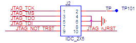
The 96Boards specification does not call for a dedicated JTAG connector. However the B2260 Development Board has JTAG signal routed to J2.
The J2 connector has a standard 10 pins JTAG connector pitch and is populated on the board as follow.
Additional Functionality
< Use this section to describe any additional functionality you’ve added to the board besides what is mandated in the 96boards spec, each in their own sub-section e.g. JTAG, GPS, Mic, SATA, PCIe, additional expansion connectors >
Expansion Connectors
Following the 96Boards requirement, two connectors are implemented on the B2260 Development Board, a high and a low speed connectors.
Note: NC refers to Not Connected PIN.
Low Speed Expansion Connector
| B2260 Signals | 96Boards Signals | PIN | PIN | 96Boards Signals | B2260 Signals | |:——————–|:——————|:——|——:|——————-:|——————–:| | GND | GND | 1 | 2 | GND | GND | | UART0_CTSO | UART0_CTS | 3 | 4 | PWR_BTN_N | NC | | UART0_TXDO | UART0_TxD | 5 | 6 | RST_BTN_N | RST_BTN_N | | UART0_RXDO | UART0_RxD | 7 | 8 | SPI0_SCLK | SPI0_SCLKO | | UART0_RTSO | UART0_RTS | 9 | 10 | SPI0_DIN | SPI0_DIN | | UART1_TXDO | UART1_TxD | 11 | 12 | SPI0_CS | SPI0_CSO | | UART1_RXDO | UART1_RxD | 13 | 14 | SPI0_DOUT | SPI0_DOUT | | I2C0_SCLO | I2C0_SCL | 15 | 16 | PCM_FS | PCM_FSO | | I2C0_SDAO | I2C0_SDA | 17 | 18 | PCM_CLK | PCM_CLKO | | I2C1_SCLO | I2C1_SCL | 19 | 20 | PCM_DO | PCM_DO | | I2C1_SDAO | I2C1_SDA | 21 | 22 | PCM_DI | PCM0_DI | | GPIO_AO | GPIO-A | 23 | 24 | GPIO-B | GPIO-BO | | GPIO_CO | GPIO-C | 25 | 26 | GPIO-D | GPIO-DO | | GPIO_EO | GPIO-E | 27 | 28 | GPIO-F | GPIO-FO | | GPIO_GO | GPIO-G | 29 | 30 | GPIO-H | GPIO-HO | | GPIO_IO | GPIO-I | 31 | 32 | GPIO-J | GPIO-JO | | GPIO_KO | GPIO-K | 33 | 34 | GPIO-L | GPIO-LO | | 1V8_CPU | +1V8 | 35 | 36 | SYS_DCIN | SYS_DCIN_12V | | 5V_AO | +5V | 37 | 38 | SYC_DCIN | SYS_DCIN_12V | | GND | GND | 39 | 40 | GND | GND |
UART {0/1}
- The 96Boards specifications calls for a 4-wire UART implementation, UART0 and an optimal second 2-wire UART, UART1 on the Low Speed Expansion Connector.
- The B2260 Development Board implements UART0 as a 4-wire UART that connects directly to the Cannes2-STiH410 SoC. These signals are driven at 1.8V.
- The B2260 Development Board implements UART1 as a 4-wire UART that connects directly to the Cannes2-STiH410 SoC. These signals are driven at 1.8V.
I2C {0/1}
- The 96Boards specification calls for two I2C interfaces to be implemented on the Low Speed Expansion Connector.
- The B2260 Development Board implements both interfaces named I2C0 and I2C1. They connect directly to the Cannes2-STiH410 SoC.
GPIO {A-L}
The 96Boards specification calls for 12 GPIO lines to be implemented on the Low Speed Expansion Connector. Some of these GPIOs may support alternate functions for DSI/CSI control
The B2260 board implements 12 GPIO but none of them support alternate functions for DSI/CSI. All GPIOs are routed to the Cannes2-STiH410 SoC.
SPI 0
The 96Boards specification calls for one SPI bus master to be provided on the Low Speed Expansion Connector.
The B2260 Development Board implements a full SPI master with 4 wires, CLK, CS, MOSI and MISO. The signals are connected directly to the Cannes2-STiH410 SoC and driven at 1.8V.
PCM/I2S
The 96Boards specification calls for one PCM/I2S bus to be provided on the Low Speed Expansion Connector. The CLK, FS and DO signals are required while the DI is optional.
The B2260 Board implements a PCM/I2S interface with 4 wires, CLK, FS, DO and DI. The signals are connected directly to the Cannes2-STiH410 SoC.
Reset
The 96Boards specification calls for a signal on the Low Speed Expansion Connector that can power on/off the board and a signal that serves as a board reset signal.
The B2260 Development Board routes the RST_BTN_N signal to the Cannes2-STiH410 SoC.
Power Supplies
The 96Boards specification calls for three power rails to be present on the Low Speed Expansion Connector:
- +1.8V Max of 100mA
- +5V Provide a minimum of 5W of power (1A).
The B2260 Development Board reaches those requirements.
High Speed Expansion Connector
| B2260 Signals | 96Boards Signals | PIN | PIN | 96Boards Signals | B2260 Signals |
|---|---|---|---|---|---|
| EXT_SD_DAT0 | SD_DAT0/SPI1_DOUT | 1 | 2 | CSI0_C+ | NC |
| EXT_SD_DAT1 | SD_DAT1 | 3 | 4 | CSI0_C- | NC |
| EXT_SD_DAT2 | SD_DAT2 | 5 | 6 | GND | GND |
| EXT_SD_DAT3 | SD_DAT3/SPI1_CS | 7 | 8 | CSI0_D0+ | NC |
| EXT_SD_SCLK | SD_SCLK/SPI1_SCLK | 9 | 10 | CSI0_D0- | NC |
| EXT_SD_CMD | SD_CMD/SPI1_DIN | 11 | 12 | GND | GND |
| GND | GND | 13 | 14 | CSI0_D1+ | NC |
| NC | CLK0/CSI0_MCLK | 15 | 16 | CCSI0_D1- | NC |
| NC | CLK1/CSI1_MCLK | 17 | 18 | GND | GND |
| GND | GND | 19 | 20 | CSI0_D2+ | NC |
| NC | DSI_CLK+ | 21 | 22 | CSI0_D2- | NC |
| NC | DSI_CLK- | 23 | 24 | GND | GND |
| GND | GND | 25 | 26 | CSI0_D3+ | NC |
| NC | DSI_D0+ | 27 | 28 | CSI0_D3- | NC |
| NC | DSI_D0- | 29 | 30 | GND | GND |
| GND | GND | 31 | 32 | I2C2_SCL | I2C2_SCLO |
| NC | DSI_D1+ | 33 | 34 | I2C2_SCL | I2C2_SDAO |
| NC | DSI_D1- | 35 | 36 | I2C3_SDA | I2C3_SCLO |
| GND | GND | 37 | 38 | I2C3_SDA | I2C3_SDAO |
| NC | DSI_D2+ | 39 | 40 | GND | GND |
| NC | DSI_D2- | 41 | 42 | CSI1_D0+ | NC |
| GND | GND | 43 | 44 | CSI1_D0- | NC |
| NC | DSI_D3+ | 45 | 46 | GND | GND |
| NC | DSI_D3- | 47 | 48 | CSI1_D1+ | NC |
| GND | GND | 49 | 50 | CSI1_D1- | NC |
| USB_D+ | USB_D+ | 51 | 52 | GND | GND |
| USB_D- | USB_D- | 53 | 54 | CSI1_C+ | NC |
| GND | GND | 55 | 56 | CSI1_C- | NC |
| NC | HSIC_STR | 57 | 58 | GND | GND |
| NC | HSIC_DATA | 59 | 60 | RESERVED | 10K pull up to 1.8V |
MIPI DSI 0
The 96Boards specification calls for a MIPI-DSI to be present on the High Speed Expansion Connector. A minimum of one lane is required and up to four lanes can be accommodated on the connector.
The B2260 Development Board implementation doesn’t support this requirement.
MIPI CSI {0/1}
The 96Boards specification calls for two MIPI-CSI interfaces to be present on the High Speed Expansion Connector. Both interfaces are optional. CSI0 interface can be up to four lanes while CSI1 is up to two lanes.
The B2260 Development Board implementation doesn’t support this requirement.
I2C {2/3}
The 96Boards specification calls for two I2C interfaces to be present on the High Speed Expansion Connector. Both interfaces are optional unless a MIPI-CSI interface has been implemented. Then an I2C interface shall be implemented.
The B2260 Development Board implementation supports 2 I2C interfaces.
SD/SPI
The 96Boards specification calls for an SD interface or a SPI port to be part of the High Speed Expansion Connector.
The B2260 Development Board implementation supports SD interface.
Clocks
The 96Boards specification calls for one or two programmable clock interfaces to be provided on the High Speed Expansion Connector. These clocks may have a secondary function of being CSI0_MCLK and CSI1_MCLK. If these clocks can’t be supported by the SoC than an alternative GPIO or No-Connect is allowed by the specifications.
The B2260 Development Board implementation doesn’t support this requirement as neither MIPI-CSI nor MIPI-DSI is supported.
USB
The 96Boards specification calls for a USB Data line interface to be present on the High Speed Expansion Connector.
The B2260 Development Board implements this requirement by routing USB channel 3 from the USB HUB to the High Speed Expansion Connector.**
HSIC
The 96Boards specification calls for an optional MIPI-HSIC interface to be present on the High Speed Expansion Connector.
The B2260 Development Board implementation doesn’t support this requirement.
Others
< Use this section to describe any additional expansion connectors and how to use the signals on them>
Power Management Overview
Block Diagram

DC Power Input
The power is provided to the system by 5 power Bucks (identified by DC/DC boxes on the scheme above) :
- one for the 5V,
- one for the 3.3V,
- one for the CPU,
- one for the Core,
- one for the LMI domain.
The 1.8V is provided by an LDO that use the 3.3V. All the Bucks operated immediately when the DC power is applied on the CN5 Jack or on SYSTEM_12V_DCIN pins on the Low Speed connector.
Power Source Selection and Sequencing
B2260 Development Board doesn’t propose any power selection scenario.
Therefore the user should never apply at the same time power on the board from the Low Speed Expansion connector (only the SYS_DCIN_12V) and from the DC jack CN5.
Please note that on the B2260 Development Board, the power can be as lower as 4.2V
Voltage Rails
Please note that there is no independent power domain on the B2260 Development Board therefore no power sequencing. When the SYS_DCIN_12V is powered from 4.2V to 18V, all the Bucks will operate therefore feeding all powers domains.
Mechanical Specification
2D Reference Drawing
