HiKey User Manual
Table of Contents
- Table of Contents
- Introduction
- Whats in the Box
- Board Overview
- System Block Diagram
- Getting Started
- Component Details
- Expansion Connectors
- Power Management Overview
- Mechanical Specification
Introduction
The HiKey board is the first board to be certified 96Boards Consumer Edition compatible, and it’s based around the HiSilicon Kirin 620 (also called Hi6220) SoC, with eight-core ARM Cortex-A53 64-bit CPU up to 1.2GHz .


- Processor:
- HiSilicon Kirin 620 SoC
- Integrated octa-core 64-bit ARM Cortex-A53 CPU up to 1.2 GHz per core
- Embedded Mali450-MP4 GPU, supporting 3D graphics processing, OpenGL ES 1.1/2.0,OpenVG 1.1, 2000Mega@500 MHz, 110M triangle@500 MHz, and 32G flops@500MHz
- Memory / Storage:
- 1GB/2GB 800MHz LPDDR3
- 8GB eMMC on-board storage
- Video:
- Embedded video hardware encoder, supporting 1080p@30 fps HD camera
- Embedded video hardware decoder, supporting 1080p@30 fps HD video decoding in the following formats: H.264, SVC, MPEG1/2/4, H.263, VC-1, WMV9, DivX, RV8/9/10,AVS
- Camera Support:
- One 4-lane MIPI camera serial interface (CSI), one 2-lane MIPI CSI
- Audio:
- WMA/MP3/AAC/EVS audio encoding and decoding
- Connectivity:
- WLAN 802.11 b/g/n 2.4GHz
- Bluetooth® wireless technology 4.0 LE
- One USB 2.0 micro B (device mode only)
- Two USB 2.0 (host mode only)
- HDMI
- I/O Interfaces:
- 40 pin low speed expansion connector:
- +1.8V, +5V, SYS_DCIN, GND, UART, I2C, SPI, PCM, PWM,GPIO x12
- 60 pin high speed expansion connector:
- SDIO, MIPI_DSI, MIPI_CSI, I2C , USB2.0
- 40 pin low speed expansion connector:
- EXternal Storage:
- Micro SD card slot
- User Interface:
- Power/Reset
- 1 WiFi activity LED(Yellow)
- 1 BT activity LED (Blue)
- OS Support:
- Android 6.0
- Linux based on Debian
- OpenEmbedded
- Mechanical:
- Dimensions: 54mm by 85mm meeting 96Boards™Consumer Edition standard dimensions specifications.
- Power:
- 8V-18V@2A input
- Environmental:
- Operating Temp: 0°C to +70°C
What’s in the Box
The box contains a HiKey board, a power supply adapter cable, a product instruction manual and a statement for GPU library.

Board Overview


System Block Diagram

Getting Started
Prerequisites
Before you power up your HiKey board for the first time you will need the following:
- HiKey board.
- A power supply with 12V@2A (suggested).
- A HDMI or DVI LCD Monitor.
- HDMI-HDMI cable or HDMI-DVI cable to connect the board to the Monitor.
- A computer keyboard with USB interface.
- A computer mouse with USB interface.
Known Limitations
- The microUSB OTG port may be used (in host or slave mode) or the Type A host ports may be used. They may notboth be used simultaneously. If a cable is inserted into the OTG port then the Type A ports and the expansion bus port will be automatically disabled.
- For the microUSB OTG port a single Low Speed (1.5Mbit/sec), Full Speed (12Mbit/sec) or High Speed (480Mbit/sec) device is supported.
- For the USB host ports all attached USB devices must be one of the following three options: Low Speed (1.5Mbit/sec) and Full Speed (12Mbit/sec) devices, or High Speed devices (480Mbit/sec).
If a mixture of High Speed and Low/Full speed devices are attached the devices will not operate correctly. This also applies if any hubs are attached to the ports.
Starting the board for the first time
To start the board, follow these simple steps:
- Connect the HDMI cable to the HiKey HDMI connector and to the LCD Monitor.
- Connect the keyboard to the boards USB connector and the mouse to the USB connector.
- Closed the auto power jumper, please see the “Jumpers/Switch Configuration”.
- Connect the power supply to power connector P301.
Once you plug the power supply into a power outlet the board will start the booting process, and you should see Debian/Android boot up.
Component Details
Processor
The HiSilicon Kirin 620 SoC is an Integrated octa-core 64-bit ARM Cortex-A53 application processor, supports 533MHz LPDDR2, 667MHz LPDDR3, and 800MHz LPDDR3 interface, MIPI camera serial interface, embedded Mali450-MP4 GPU,1080p video encode/decode, GPS, WIFI, Bluetooth 4.1, OpenGL ES 1.1/2.0,OpenVG 1.1, ARM TrustZone security mechanism.
PMIC
HI6553V100 is a power management chip, with integrated 4-channel BUCK, 24 LDO, 1 LVS (Low Voltage Switch), a 12-channel HKADC, and 5-channel LED current driver ports. It supports under-voltage, over-voltage, over-heat, over-current protection. BUCK1 supports 3.5A output capacity, BUCK2 has 3A output capacity, while BUCK3 and BUCK4 have 1A output capability.
In addition, there’re built-in 32K Crystal and 19.2M Crystal oscillation circuits. Correspondingly there’re also 3-channel 32K digital clock output, 5-channel 19.2M analog clock output, and 1-channel 19.2M digital clock output.
Memory (DRAM)
The HiKey (LeMaker version) uses a LPDDR3 DRAM chip as the memory. It provides 1GB or 2GB DRAM memory to satisfy the different requirements. a single embedded Multi Chip Package (eMCP) dual function LPDDR3/eMMC memory solution. The LPDDR3 is a 32bit width bus implementation interfacing directly to the Kirin 620 build-in LPDDR controller. The maximum DDR clock is 800Mhz. We can distinguish the memory capacity by the footprint on the memory chip:
| Serial | Size |
|---|---|
| K4E8E304EE-EGCE | 1GB |
| K4E6E304EE-EGCE | 2GB |
Storage
eMMC
The Hikey (LeMaker version) has an on-board 8GB eMMC nand flash. The eMMC is an 8bit implementation interfacing with Kirin 620 eMMC interface supporting eMMC 4.5 specifications. and supports 1-bit, 4-bit, and 8-bit modes.
Micro SDHC
The microSDHC socket is on the bottom left corner of the PCB and is routed directly to the Kirin 620 SD 3.0 interface, and supports 1-bit and 4-bit modes (3 V and 1.8 V supported for the I/O device). The slot is a push-push type with a dedicated support for card detect signal.
Boot ROM
The MediaTek X20 Development Board boots up from the EMMC.
Networking
WiFi/Bluetooth LE
The HiKey board uses a TI WL1835MOD WLAN Baseband Processor and RF Transceiver which supports IEEE 802.11b, 802.11g and 802.11n WiFi and Bluetooth 4.0 (including low energy).
More features about the TI WL1835MOD can refer to:
http://processors.wiki.ti.com/index.php/WL18xx_Overview
Display Interface
As a display channel of the HI6220V100 chip, the ADE overlays graphics layers,and controls display timings. The ADE supports the RGB parallel interface that can connect to display interface IPs such as the MIPI DSI and HDMI. Below is a block diagram of the HiKey implementation.

HDMI
The Kirin 620 doesn’t include a built-in HDMI interface. The Kirin 620 deploys the built-in MIPI-DSI 4 lanes interface as the source for the HDMI output. A peripheral DSI to HDMI Bridge (Analog Devices ADV7533) performs this task and it supports a resolution from 480i to 1080p at 30Hz.While the ADV7533 supports automatic input video form at timing detection (CEA-861E), an I2C channel from the Kirin 620 allows the user to configure the operation of this bridge. This bridge supports audio as well (meeting the 96Boards requirements to provide audio via HDMI). Please note that the 96Boards specification calls for a MIPI-DSI interface to be routed to the High Speed Expansion connector. Since the Kirin 620 has only one MIPI-DSI interface. A mux device (FSA644UCX) is being used on the board. Only one interface, HDMI, or the Expansion MIPI-DSI can be active at a given time. The controlling signal is named‘ DSI_SEL_GPIO0_1’. When this signal is logic low, ‘0’, the MIPI-DSI is routed to the DSI-HDMI Bridge. When‘ DSI_SEL_GPIO0_1’ is logic level high, ‘1’, the MIPI-DSI is routed to the High Speed Expansion connector.
MIPI-DSI
Expansion connector.The Kirin 620 implemented a four-lane MIPI_DSI interface meeting this requirement. More information about this implementation can be found in High Speed Expansion Connector.
Camera Interface
The HiKey board implements two camera interfaces, one with a four-lane MIPI_CSI interface and one with a two-lane MIPI_CSI interface, meeting this requirement. More information about this implementation can be found in High Speed Expansion Connector.
USB Ports
There are a total of 4 USB ports on the HiKey board. Two Type-A host ports at J401 and J403, one microUSB AB 2.0 host/slave port at J402 and one USB host port available on the High Speed Expansion bus. The following block diagram shows the HiKey board implementation:

The HiKey board utilizes a single SoC USB interface without USB protocol hardware split transfer support. The USB interfaces are therefore subject to the following restrictions:
- Either the microUSB or the Type A and LS expansion USB interfaces may be used at a time, depending on the state of USB_SEL_GPIO0_3. Both interfaces may not be used at the same time.
- The microUSB port supports a single attached device with USB slave operations or USB host high speed, full speed or low speed operations.
- The Type A and LS expansion USB interface cannot support mixed speed devices. All attached devices must be of the same type – high speed, full speed or low speed.Furthermore, the HiKey board must be configured in software to support either full speed/low speed devices (default) or high speed devices on these ports.
Audio
The HiKey board uses HDMI audio as the audio output. It also has a PCM channel on the Low Speed Expansion connector.
DC Power
The 96Boards specification calls for power to be provided to the board in one of the following ways:
- An 8V to 18V power from a dedicated DC jack .
- An 8V to 18V power from the SYS_DCIN pins on the Low Speed Expansion Connector.
- Powering via USB is forbidden.
An 8V up to 18V power supply at a minimum of 2A rating can be used to provide sufficient board power for on system requirements as well as external devices. Additional current rating may be required for mezzanine boards or modules. DC Power can also be supplied via the SYS_DCIN pins on the low speed expansion. Please see the detail information in the DC Power Input section for detailed information on Kirin 620 implementation of DC Power.
Power Measurement
The 96Boards specification calls for support for measuring power consumptions of the board. Please see the detail information in the Power Management section for the HiKey Power Measurement implementation.
External Fan Connection
The HiKey board can drive 5V or 12V cooling fans. The power for these is available on the low speed Expansion connector and can be supplied through a 2-pin 2mm male header inserted at pins SYS_5V or SYSDC_IN.
UART
The HiKey board also has an option for a Debug UART Header. This is normally used by the first stage bootloader developers, and is connected to the UART0 port of the SoC. This is available if a 2x2 male header is installed at J801. See below for the pin out of this header.
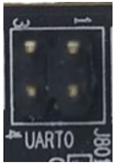
| Signal | Pin | Pin | Signal |
|---|---|---|---|
| 1.8V | 1 | 2 | UART0_RX |
| DGND | 3 | 4 | UART0_TX |
And HiKey also has other UART(UART2 and UART3) on the Low Speed Expansion connector.
Please note:at now all the Linaro reference build Linux distribution will use the UART3 on the HiKey board as the debug UART
Buttons
The 96Boards specification calls for the present of two buttons, a Power on/sleep button and a Reset button. The HiKey meets these requirements. The power button S601 can be used to power up, power down, and reset the system. The circuit is designed such that the user will be able to manually power up, down and reset the board.
- A press and hold will power off the board if the Auto Power Jumper is not installed.
- A press and release will then power off the board.
- A press and hold for >4 seconds will reset the board.
It is also possible to connect external switches for power on/off and for hard reset.
LED Indicators
The 96Boards specifications calls for six LEDs to be implemented on the board. The specification defines the LEDs color and mechanical location on the board. There are two status LEDs and four User LEDs on the HiKey board. The user LEDs can be programmed by the SoC directly.
Two activity LEDs
- The WiFi activity LED is a Yellow type surface mount 0603 LED. The WIFI LED on the HiKey is located beside the BT LED, this LED reflects the status of the Wi-Fi device.
- The BT activity LED is a Blue Type surface mount 0603 LED. The BT LED on the HiKey board is located next to the USB OTG connector; this LED reflects the status of the Bluetooth device.
Four User LEDs
The four user LEDs are surface mount Green Type 0603 LED.
Additional Functionality
JTAG
The HiKey board includes the option for soldering a 10 pin header that brings out the SoC signals for JTAG debug. A FTSH-105-01-F-DV header can be populated at J803.
Expansion Connectors
The HiKey board features two expansion connectors: one low speed expansion connector and one high speed.
Low Speed Expansion Connector
The low speed expansion connector carries GPIO and other low speed interfaces. The connector is a low profile 40 pin female 2mm receptacle (20x2) of a specified height of 4.5mm height. The low speed expansion brings out 1.8V level SoC signals such as UART2 and UART3, I2C0 and I2C1, GPIO signals as well as SPI, PCM, Reset, 1.8V and Ground.
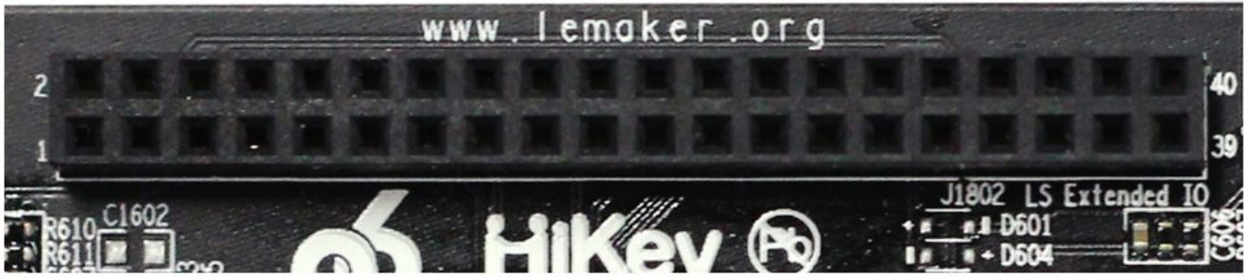
The following tables show the Low Speed Expansion Connector pin out:
| HiKey Signals | 96Boards Signals | PIN | PIN | 96Boards Signals | HiKey X20 Signals |
|---|---|---|---|---|---|
| DGND | GND | 1 | 2 | GND | DGND |
| UART2_CTS_N | UART0_CTS | 3 | 4 | PWR_BTN_N | PMU_PWRON_N |
| UART2_TX | UART0_TxD | 5 | 6 | RST_BTN_N | EXP_RSTOUT_N |
| UART2_RX | UART0_RxD | 7 | 8 | SPI0_SCLK | SPI0_SCLK |
| UART2_RTS_N | UART0_RTS | 9 | 10 | SPI0_DIN | SPI0_DI |
| UART3_TX | UART1_TxD | 11 | 12 | SPI0_CS | SPI0_CS_N |
| UART3_RX | UART1_RxD | 13 | 14 | SPI0_DOUT | SPIO_DO |
| I2C0_SCL | I2C0_SCL | 15 | 16 | PCM_FS | MODEM_PCM_XFS |
| I2C0_SDA | I2C0_SDA | 17 | 18 | PCM_CLK | MODEM_PCM_XCLK |
| I2C1_SCL | I2C1_SCL | 19 | 20 | PCM_DO | MODEM_PCM_DO |
| I2C1_SDA | I2C1_SDA | 21 | 22 | PCM_DI | MODEM_PCM_DI |
| GPIO2_0 | GPIO-A | 23 | 24 | GPIO-B | GPIO2_1 |
| GPIO2_2 | GPIO-C | 25 | 26 | GPIO-D | GPIO3_3 |
| GPIO2_4 | GPIO-E | 27 | 28 | GPIO-F | BL_PWM_GPIO12_7 |
| GPIO6_7_DSI_TE0 | GPIO-G | 29 | 30 | GPIO-H | GPIO2_7 |
| ISP_RSTB0_GPIO10_3 | GPIO-I | 31 | 32 | GPIO-J | ISP_PWDN0_GPIO9_1 |
| ISP_RSTB1_GPIO10_3 | GPIO-K | 33 | 34 | GPIO-L | ISP_PWDN0_GPIO9_2 |
| LDO21_1V8 | +1V8 | 35 | 36 | SYS_DCIN | SYSDC_IN |
| SYS_5V | +5V | 37 | 38 | SYC_DCIN | SYSDC_IN |
| DGND | GND | 39 | 40 | GND | DGND |
UART {0/1}
The HiKey board implements UART2 as a 4-wire UART that connects directly to the Kirin
- These signals are driven at 1.8V.
The HiKey board implements UART3 as a 2-wire UART that connects directly to the Kirin
- These signals are driven at 1.8V.
I2C {0/1}
The HiKey board implements both interfaces, I2C0 and I2C1 that connects directly to the Kirin 620
GPIO {A-L}
The Kirin 620 has 20 groups of general-purpose input/output (GPIO) pins, including GPIO0−GPIO2 in the power-on area of the system-on-chip (SoC) system and GPIO3−GPIO19 in the power-off area of the SoC system. Each GPIO group has eight programmable GPIO pins, and there are 160 GPIO pins in total. The GPIO pins are used to generate output signals or collect input signals for specific applications. The GPIO3−GPIO19 pins are multiplexed with other functional pins.
SPI 0
The HiKey board implements a full SPI master with 4 wires, CLK, CS, MOSI and MISO all connect directly to the Kirin 620.
PCM
The HiKey board implements a PCM with 3 wires, CLK, FS and DO, the optional DI signal is not implemented on the HiKey board. The I2S signals are connected directly to the Kirin 620.
Power and Reset
The 96Boards specification calls for a signal on the Low Speed Expansion Connector that can power on/off the board and a signal that serves as a board reset signal. The MediaTek X20 Development Board routes the PWR_BTN_N (named PWRKEY on schematic) signal to the PWRKEY pin of the PMIC MT6351. This signal is driven by SW3201 as well, the on-board power on push-button switch. A mezzanine implementation of this signals should not drive it with any voltage, the only allowed operation is to force it to GND to start the board from a sleep mode. The MediaTek X20 Development Board routes the RST_BTN_N (named SYSRSTB on schematic) signal to the SYSRSTB pin of the PMIC MT6351.
Power Supplies
The HiKey board routes the PMU_PWRON_N signal to the PWRON_N pin of the HI6553V100 PMIC. This signal is driven by S601 as well, the on-board power on push-button switch.
The HiKey board routes the EXP_RSTOUT_N signal to the RSTOUT_N pin of the HI6553V100 PMIC.
High Speed Expansion Connector
The HS Expansion connector is a board to board low profile 60 pin receptacle TE part number 5177983-2.Pin1 for this header is at the bottom left corner as shown.

The following table shows the High Speed Expansion Connector pin out:
| HiKey Signals | 96Boards Signals | PIN | PIN | 96Boards Signals | HiKey Signals |
|---|---|---|---|---|---|
| SD1_DATA0 | SD_DAT0/SPI1_DOUT | 1 | 2 | CSI0_C+ | CSI0_CLK_P |
| SD1_DATA1 | SD_DAT1 | 3 | 4 | CSI0_C- | CSI0_CLK_N |
| SD1_DATA2 | SD_DAT2 | 5 | 6 | GND | DGND |
| SD1_DATA3 | SD_DAT3/SPI1_CS | 7 | 8 | CSI0_D0+ | CSI0_DATA0_P |
| SD1_CLK | SD_SCLK/SPI1_SCLK | 9 | 10 | CSI0_D0- | CSI0_DATA0_N |
| SD1_CMD | SD_CMD/SPI1_DIN | 11 | 12 | GND | DGND |
| DGND | GND | 13 | 14 | CSI0_D1+ | CSI0_DATA1_P |
| ISP_CCLK0 | CLK0/CSI0_MCLK | 15 | 16 | CCSI0_D1- | CSI0_DATA1_N |
| ISP_CCLK1 | CLK1/CSI1_MCLK | 17 | 18 | GND | DGND |
| DGND | GND | 19 | 20 | CSI0_D2+ | CSI0_DATA2_P |
| DSI2_CLK_P | DSI_CLK+ | 21 | 22 | CSI0_D2- | CSI0_DATA2_N |
| DSI2_CLK_N | DSI_CLK- | 23 | 24 | GND | DGND |
| DGND | GND | 25 | 26 | CSI0_D3+ | CSI0_DATA3_P |
| DSI2_DATA0_P | DSI_D0+ | 27 | 28 | CSI0_D3- | CSI0_DATA3_N |
| DSI2_DATA0_N | DSI_D0- | 29 | 30 | GND | DGND |
| DGND | GND | 31 | 32 | I2C2_SCL | ISP0_SCL |
| DSI2_DATA1_P | DSI_D1+ | 33 | 34 | I2C2_SCL | ISP0_SDA |
| DSI2_DATA1_N | DSI_D1- | 35 | 36 | I2C3_SDA | ISP1_SCL |
| DGND | GND | 37 | 38 | I2C3_SDA | ISP1_SDA |
| DSI2_DATA2_P | DSI_D2+ | 39 | 40 | GND | DGND |
| DSI2_DATA2_N | DSI_D2- | 41 | 42 | CSI1_D0+ | CSI1_DATA0_P |
| DGND | GND | 43 | 44 | CSI1_D0- | CSI1_DATA0_N |
| DSI2_DATA3_P | DSI_D3+ | 45 | 46 | GND | DGND |
| DSI2_DATA3_N | DSI_D3- | 47 | 48 | CSI1_D1+ | CSI1_DATA1_P |
| DGND | GND | 49 | 50 | CSI1_D1- | CSI1_DATA1_N |
| USBDP3 | USB_D+ | 51 | 52 | GND | DGND |
| USBDM3 | USB_D- | 53 | 54 | CSI1_C+ | CSI1_CLK_P |
| DGND | GND | 55 | 56 | CSI1_C- | CSI1_CLK_N |
| NOT USED | HSIC_STR | 57 | 58 | GND | DGND |
| NOT USED | HSIC_DATA | 59 | 60 | RESERVED | 100K PU TO LDO5_1V8 |
MIPI DSI 2
The 96Boards specification calls for a MIPI-DSI to be present on the High Speed Expansion Connector. A minimum of one lane is required and up to four lanes can be accommodated on the connector.
The HiKey board implementation supports a full four lane MIPI-DSI interface that is routed to the High Speed Expansion Connector. Since the Kirin 620 has only single MIPI-DSI interface and it may be used to drive the DSI-HDMI Bridge, DSI Muxing is required. A mux device, U1702 (FSA644UCK) is used on the board. Only one interface, HDMI, or the Expansion MIPI-DSI can be active at a given time. The controlling signal is named ‘ DSI_SEL_GPIO0_1’. When this signal is logic low, ‘0’, the MIPI-DSI is routed to the DSI-HDMI Bridge.
When ‘ DSI_SEL_GPIO0_1’ is logic level high, ‘1’, the MIPI-DSI is routed to the High Speed Expansion connector.
MIPI CSI {0/1}
The 96Boards specification calls for two MIPI-CSI interfaces to be present on the High
Speed Expansion Connector. Both interfaces are optional. CSI0 interface can be up to four lanes while CSI1 is up to two lanes.
The current HiKey board implementation supports a full four-lane MIPI-CSI interface on CSI0 and a two-lane of MIPI-CSI on CSI1. All MIPI-CSI signals are routed directly to/from the Kirin 620.
USB
The 96Boards specification calls for a USB data line interface to be present on the High Speed Expansion Connector. The HiKey board implements this requirements by routing USB channel 3 from the USB HUB to the High Speed Expansion Connector.
Power Management Overview
Block Diagram

The 96Boards specification defines how power arrives to the board and few supplies that the board needs to provide. The on board power requirement for each 96Boards implementation depends on the SoC and the set of peripherals that are specific to that implementation. The HiKey board uses two buck regulators, U302 and U301. U302 takes the power into the board and generates 5V at 4A. This voltage feeds the USB HOST power limit switches and provides power to the Low Speed Expansion port. U301 takes the power into the board and generates 4.2V at 4A. This voltage serves as the power in voltage to the on-board PMIC, HI6553V100. The HI6553V100 can generate 22 different voltage rails.
DC Power Input
The HiKey board can be powered from one of the following ways: power to be provided in one of the following ways:
- 8V to 18V supply from a dedicated DC jack. The HiKey board supports this requirement through the use of P301, ‘SYS_DCIN’ power connector.
Please note: the SYS_DCIN can be as low as 6.5V on the HiKey board. The power supply which is used to power the board from the DC jack should be positive outside and negative inside.
- 8V to 18V supply from the SYS_DCIN pins on the Low Speed Expansion Connector. The HiKey board supports incoming power through this connector.
Please note:the SYS_DCIN can be as low as 6.5V on the HiKey board.
Power Source Selection and Sequencing
The HiKey board has only two sources for board incoming power. The 96Boards specification calls for only one power source to be applied to the board at any given time. Following this requirement, the user of the HiKey board should never apply power to the board from P301 and the SYS_DCIN on the Low Speed Expansion connector at the same time. There is no active or passive mechanism on the HiKey board to prioritize one source over the other.
Power Measurements
The HiKey board supports power measurement for instrumentation and testing. 0.001ohm 1206 sense resistors can be used. Installed at specific locations in place of the 0Ωresistors currently populated on the board. To connect to these sense resistors, the PCB provides footprints for 100mm 2-pin headers that can be installed. For voltage measurements, digital GND is provided on the low speed expansion connector.The HiKey board was designed to provide current measurements for the following rails:
| Resistor | Header | Rail | Measurement |
|---|---|---|---|
| R302 | J301 | DC_IN | Total Base Board Power |
| R306 | VDD_4V2 | PMIC | |
| R305 | SYS_5V | HDMI, USB |

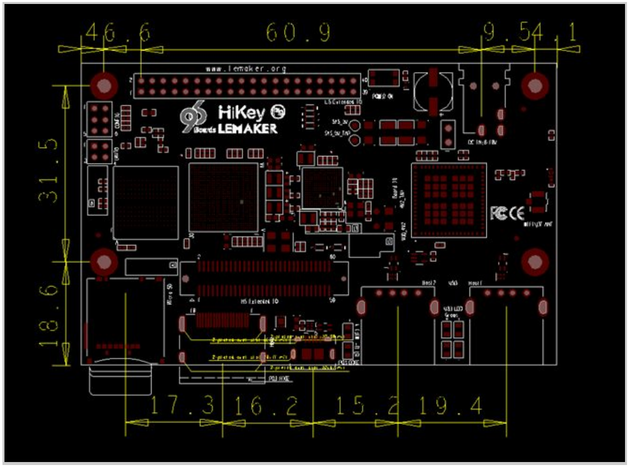
Mechanical Specification
2D Reference Drawing