HiKey960 Development Board User Manual
Table of Contents
- Table of Contents
- Introduction
- What’s in the Box
- Board Overview
- System Block Diagram
- Getting Started
- Component Details
- Expansion Connectors
- Power Management Overview
Introduction
The HiKey960 Development Board is a 96Boards compliant community board based on Hisilicon Kirin960 SoC. The following table lists its key features:


- Kirin 960 SoC:
- 4Cortex A73 + 4Cortex A53 Big.Little CPU architecture
- ARM Mali G71 MP8
- 3GB LPDDR4 SDRAM
- Hi6421GWCV530 PMU
- Memory / Storage:
- 32GB UFS flash storage
- MicroSD card slot
- PCIe Gen2 on M.2 M Key connector
- Wireless:
- WiFi (2.4- and 5-GHz dual band with two antennas)
- Bluetooh 4.1
- USB
- 2 x USB 3.0 type A (host mode only)
- 1 x USB 2.0 type C OTG
- Display
- 1 x HDMI 1.4 (Type A - full)
- 1 x 4L-MIPI DSI
- HDMI output up to FHD 1080P
- Video
- Inside Encoder:H.265/H.264 3840*2400@30fps 4 * 1080p @ 30 fps
- Inside Decoder: H.265,HEVC MP/High Tier, Main 10/High Tier,H.264 BP/MP/HP, MPEG1/2/4, VC-1, VP6/8
- Audio
- HDMI output
- Camera
- 1 x 4-lane MIPI CSI
- 1 x 2-lane MIPI CSI
- Expansion Interface
- 40 pin low speed expansion connector: +1.8V, +5V, DC power, GND, 2UART, 2I2C, SPI, I2S, 12*GPIO
- 60 pin high speed expansion connector: 4L-MIPI DSI, I2C x2, SPI (48M), USB 2.0, 2L+4LMIPI CSI
- LED
- 1 x WiFi activity LED(Yellow)
- 1 x BT activity LED (Blue)
- 4 x User LEDs (Green)
- Button
- Power Button : Button Power on/off & Reset the system
- Power Source
- Recommend a 12V@2A adapter with a DC plug which has a 4.75mm outer diameter and 1.7mm center pin with standard center-positive (EIAJ-3 Compliant)
- OS Support
- AOSP/LINUX
- Appearance characteristic
- 85mm x 55mm
What’s in the Box
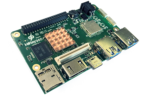
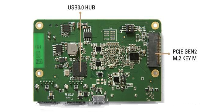
Board Overview

| Position | Description |
|---|---|
| 1 | 40PIN low speed interface |
| 2 | Power interface |
| 3 | SD Card |
| 4 | HDMI A |
| 5 | USB 2.0 OTG TYPE C |
| 6 | USB 3.0 |
| 7 | USB 3.0 |
| 8 | 4 leds |
| 9 | 60 PIN High speed |
| 10 | WLAN And Bluetooth |
| 11 | BOOT Select |
| 12 | DEBUG Uart |
| 13 | POWER/RESET |
| 14 | WLAN/Bluetooth antenna |
| 15 | PCIE M2 MKEY |
| 16 | JTAG |

System Block Diagram

Jumpers/Switch Configurations
Getting Started
Prerequisites
Before you power up your HiKey960 Development Board for the first time you will need the following:
- HiKey960 Development Board.
- A 96Boards compliant power supply (sold separately ).
- A HDMI or DVI LCD Monitor that supports a resolution of 1080P/60Hz.
- HDMI-HDMI cable or HDMI-DVI cable to connect the board to the Monitor.
- A computer keyboard with USB interface.
- A computer mouse with USB interface.
Known Limitations
Starting the board for the first time
To start the board, follow these simple steps:
- Connect the HiKey960 to your display with the HDMI cable. It is important to do this first because the monitor will not detect the board if it is connected after starting. Ensure that the source for the display is switched to the HDMI port you are using.
- Connect the Express-UartBoard.
- Ensure Auto Power is ON.
Component Details
Processor
- 4 ARM Cortex-A73 MPCore(Big Core 4 2.4G Hz) 4 A53 MPCore(Little Core 1.8G)
- ARM Mali G71 MP8 3DGPU
PMIC
- There are a master PMIC and two slave PMIC for Kirin960 platform.
- Master PMIC is a power management system chip.
- One of the slave PMIC is a 4-phase high efficiency buck converter which applied to offer the power of CPU-B, and the other one is used for GPU&CPU-L.
Memory (DRAM)
The Hikey960 Development Board provides 3GB LPDDR4-SDRAM which is a 4-channel and 64bit width bus implementation interfacing directly to the Kirin960 build-in LPDDR controller. The maximum DDR clock is 1866MHz. It is mounted over the Kirin960 using pop technology.
Storage
The Hikey960 Development Board provides an 32GB UFS which is compliant with UFS2.0.
Micro SDHC
The Hikey960 Development Board SD slot signals are routed directly to the Kirin960 SDC interface. It meets the SD3.0 standard.
Boot ROM
The Hikey960 Development Board boots up from the UFS.
Networking
WiFi
- Dual-band (2.4/5GHz) single stream 802.11 a/b/g/n RF.
- 20- and 40-MHz SISO and 20-MHz 2 × 2 MIMO at 2.4 GHz for High Throughput: 80 Mbps(TCP), 100 Mbps (UDP).
- 2.4-GHz MRC Support for Extended Range and 5-GHz Diversity Capable.
Bluetooth
- Bluetooth® wireless technology 4.1 Compliance and CSA2 Support.
- Host Controller Interface (HCI) Transport for Bluetooth Over UART.
- Dedicated Audio Processor Support of SBC Encoding + A2DP.
- Dual-Mode Bluetooth and Bluetooth LE.
Display Interface
HDMI
- The 96Boards specification calls for an HDMI port to be present on the board. The Kirin960 doesn’t include a built-in HDMI interface.
- The Hikey960 Development Board deploys the built-in DSI interface as the source for the HDMI output. A peripheral Bridge IC (U1901, ADV7535) performs this task and it supports 1080p at 30Hz.
MIPI-DSI
- The 96Boards specification calls for a MIPI-DSI implementation via the High Speed Expansion Connector.
- The Hikey960 Development Board implements a 4-lane MIPI_DSI interface meeting this requirement. It can support up to 2560*1600@60fps. The Hikey960 Development Board routes the MIPI_DSI interface signals to the DSI-0 interface of the Kirin960.
Camera Interface
- The 96Boards specification calls for two camera interfaces.
- The Hikey960 Development Board supports two camera interfaces, one with a 4-lane MIPI_CSI interface and one with 2-lane MIPI_CSI interface, meeting this requirement. The 4-lane MIPI_CSI interface can support 26M camera and the 2-lane MIPI_CSI interface can support 8M camera.
USB Ports
The Hikey960 Development Board supports a USB OTG port and three USB host ports via a USB MUX. The input channel( D+/D-) of USB MUX is connected to the usb port of the SOC, and the two output channels(1D+/1D-,2D+/2D-) are connected to type C USB port and USB hub respectively. The three USB host ports are connected to the downstream ports of the USB hub.The control of MUX is done via a software controlled GPIO. When this signal is logic low, ‘0’, the USB data lines are routed to the type C USB connector. When ‘USB_SW_SEL’ is logic level high, ‘1’, the USB data lines are routed to USB HUB.
USB Host ports
The Hikey960 Development Board supports three USB host port via a USB hub (U1803 USB5734). Its upstream signal is connected to USB interface of Kirin960.
- Port 1 of the USB HUB is routed to J1702, a Type ‘A’ USB Host connector. A current limited controller (U1704) sets the Power Current limit to 1A.
- Port 2 of the USB HUB is routed to J1801, a Type ‘A’ USB Host connector. A current limited controller (U1806) sets the Power Current limit to 1A.
- Port 3 of the USB HUB is routed to the High Speed Expansion connector. No current limited controller is implemented on the board for this channel.
USB OTG ports
The Hikey960 Development Board implements a OTG port. The port is located at J1701, a type C USB.
Note: The board can work in one mode at a time, Host mode or Device mode, not both.
Audio
The Hikey960 Development Board has three audio ports: BT, HDMI and I2S.
DC Power
The Hikey960 Development Board can be powered as follow:
- 8V to 18V supply from a dedicated DC jack(P401)
Power Measurement
The Hikey960 Development Board has three current sense resistors R401/R413/R408.
| Reference | Net | Description |
|---|---|---|
| R401 | DC_IN | To measure the current of total base board power |
| R413 | SYS_5V | To measure the current of SYS_5V power |
| R408 | VDD_4V2 | To measure the current of VDD_4V2 power |


External Fan Connection
The 96Boards specification calls for support for an external fan. That can be achieved by using the 5V or the SYS_DCIN (12V), both present on the Low Speed Expansion connector.
UART
The Hikey960 Development Board has two UART ports (UART6 / UART3), both present on the Low Speed Expansion connector. They are routed to the UART6 (UART1_TxD, UART1_RxD) and UART3 (UART3_TxD, UART3_RxD, UART3_CTS, UART3_RTS) interface of Kirin960 separately. The UART6 is used for the serial console output.
Buttons
The Hikey960 Development Board presents one button. It is Power key which also can be used as Reset key. The power ON/OFF and RESET signals are also routed to the Low Speed Expansion connector.
Power Button
The push-button S2201 serves as the power-on/sleep button. Upon applying power to the board, press the power button the board will boot up. Once the board is running you can turn power-off by pressing the power button for more than 3 seconds. If the board is in a sleep mode, pressing the power bottom will wake up the board. Oppositely, if the board is in an active mode, pressing the power bottom will change the board into sleep mode.
Reset Button
The push-button S2201 also serves as the hardware reset button. press the button for more than 10 seconds,the system will be rebooted.
LED Indicators
The Hikey960 Development Board has six LEDs.
Two activity LEDs
- WiFi activity LED –The Hikey960 Development Board drives this Yellow LED via GPIO205 from Kirin960.
- BT activity LED –The Hikey960 Development Board drives this Blue LED via GPIO207 from Kirin960.
Four User LEDs
The four user LEDs are surface mount Green in 0603 size located next to the USB type A connector. The Hikey960 Development Board drives the four LEDs from the soc GPIO: GPIO150, GPIO151,GPIO189 and GPIO190.
Additional Functionality
The Hikey960 Development Board also has a additional interface for user debugging. It includes JTAG interface. The position is reserved, but the component is not mounted in the mass production.
Expansion Connectors
Low Speed Expansion Connector
| HiKey960 Signals | 96Boards Signals | PIN | PIN | 96Boards Signals | HiKey960 Signals |
|---|---|---|---|---|---|
| GND | GND | 1 | 2 | GND | GND |
| UART3_CTS_N | UART0_CTS | 3 | 4 | PWR_BTN_N | PWRON_N |
| UART3_TXD | UART0_TxD | 5 | 6 | RST_BTN_N | EXP_RSTOUT_N |
| UART3_RXD | UART0_RxD | 7 | 8 | SPI0_SCLK | SPI2_CLK |
| UART3_RTS_N | UART0_RTS | 9 | 10 | SPI0_DIN | SPI2_DI |
| UART6_TXD | UART1_TxD | 11 | 12 | SPI0_CS | SPI2_CS_N |
| UART6_RXD | UART1_RxD | 13 | 14 | SPI0_DOUT | SPI2_DO |
| I2C0_SCL | I2C0_SCL | 15 | 16 | PCM_FS | GPIO_195_I2S0_XFS |
| I2C0_SDA | I2C0_SDA | 17 | 18 | PCM_CLK | GPIO_194_I2S0_XCLK |
| I2C7_SCL | I2C1_SCL | 19 | 20 | PCM_DO | GPIO_193_I2S0_DO |
| I2C7_SDA | I2C1_SDA | 21 | 22 | PCM_DI | GPIO_192_I2S0_DI |
| GPIO_208 | GPIO-A | 23 | 24 | GPIO-B | GPIO_209 |
| GPIO_210 | GPIO-C | 25 | 26 | GPIO-D | GPIO_211 |
| GPIO_212 | GPIO-E | 27 | 28 | GPIO-F | LCD_BL_PWM |
| LCD_TE0 | GPIO-G | 29 | 30 | GPIO-H | GPIO_040_LCD_RST_N |
| GPIO_052_CAM0_RST_N | GPIO-I | 31 | 32 | GPIO-J | GPIO_019 |
| GPIO_075_CAM1_RST_N | GPIO-K | 33 | 34 | GPIO-L | GPIO_021 |
| VOUT11_1V8/2V95 | +1V8 | 35 | 36 | SYS_DCIN | SYSDC_IN |
| SYS_5V | +5V | 37 | 38 | SYC_DCIN | SYSDC_IN |
| GND | GND | 39 | 40 | GND | GND |
UART {3/6}
- The 96Boards specifications calls for a 4-wire UART implementation, UART0 and an optimal second 2-wire UART, UART1 on the Low Speed Expansion Connector.
- The HiKey960 Development Board implements UART3 as a 4-wire UART that connects directly to the main SoC. These signals are driven at 1.8V.
- The HiKey960 Development Board implements UART6 as a 2-wire UART that connects directly to the main SoC. These signals are driven at 1.8V.
I2C {0/1}
- The 96Boards specification calls for two I2C interfaces to be implemented on the Low Speed Expansion Connector.
- The HiKey960 Development Board implements both interfaces named I2C0 and I2C7. They connect directly to the Kirin960 SoC. Each of the I2C lines is pulled up to VIO18_PMU via 1K resistor.
GPIO {A-L}
The 96Boards specification calls for 12 GPIO lines to be implemented on the Low Speed Expansion Connector. Some of these GPIOs may support alternate functions for DSI/CSI control The HiKey960 board implements this requirement. All GPIOs are routed to the Kirin960 SoC. Take Low Speed Expansion Connector for reference.
SPI 0
- The 96Boards specification calls for one SPI bus master to be provided on the Low Speed Expansion Connector.
- The HiKey960 Development Board implements a full SPI master with 4 wires, CLK, CS, MOSI and MISO. The signals are connected directly to the Kirin960 SoC and driven at 1.8V.
I2S
- The 96Boards specification calls for one PCM/I2S bus to be provided on the Low Speed Expansion Connector. The CLK, FS and DO signals are required while the DI is optional.
- The HiKey960 Development Board implements a I2S interface with 4 wires, CLK, FS, DO and DI. The signals are connected directly to the Kirin960 SoC and driven at 1.8V.
Power and Reset
- The 96Boards specification calls for a signal on the Low Speed Expansion Connector that can power on/off the board and a signal that serves as a board reset signal.
- The HiKey960 Development Board routes the PWR_BTN_N (named PWRKEY on schematic) signal to the PWRKEY pin of the PMIC. This signal is driven by s2201 as well, the on-board power on push-button switch. A mezzanine implementation of this signals should not drive it with any voltage, the only allowed operation is to force it to GND to start the board from a sleep mode.
- The HiKey960 Development Board routes the RST_BTN_N (named exp_rstout_n on schematic) signal to the HRESET_N pin of the PMIC Hi6421.
Power Supplies
The 96Boards specification calls for three power rails to be present on the Low Speed Expansion Connector:
- +1.8V Max of 100mA
- +5V Provide a minimum of 5W of power (1A).
SYS_DCIN 8-18V input with enough current to support all the board functions or the output DCIN from on-board DC Connector able to provide a minimum of 7W of power.
The HiKey960 Development Board supports these requirements as follows:
- +1.8V Driven by PMIC up to 150mA.
- +5V Driven by a 5A DC-DC buck converter (U403). It also provides the VBUS power to the two USB host connectors (J1702, J1801) and the HDMI 5V power to the HDMI connector (J1901).The remaining capacity provides a total of 7W which meets the 96Boards requirements.
High Speed Expansion Connector
| HiKey960 Signals | 96Boards Signals | PIN | PIN | 96Boards Signals | HiKey960 Signals |
|---|---|---|---|---|---|
| GPIO_148_SPI3_DO | SD_DAT0/SPI1_DOUT | 1 | 2 | CSI0_C+ | CSI0_CLK_P |
| UART0_IRDA_RXD | SD_DAT1 | 3 | 4 | CSI0_C- | CSI0_CLK_N |
| UART0_IRDA_TXD | SD_DAT2 | 5 | 6 | GND | GND |
| GPIO_149_SPI3_CS0_N | SD_DAT3/SPI1_CS | 7 | 8 | CSI0_D0+ | CSI0_DATA0_P |
| GPIO_146_SPI3_CLK | SD_SCLK/SPI1_SCLK | 9 | 10 | CSI0_D0- | CSI0_DATA0_N |
| GPIO_147_SPI3_DI | SD_CMD/SPI1_DIN | 11 | 12 | GND | GND |
| GND | GND | 13 | 14 | CSI0_D1+ | CSI0_DATA1_P |
| ISP_CCLK0_MCAM | CLK0/CSI0_MCLK | 15 | 16 | CCSI0_D1- | CSI0_DATA1_N |
| ISP_CCLK1_SCAM | CLK1/CSI1_MCLK | 17 | 18 | GND | GND |
| GND | GND | 19 | 20 | CSI0_D2+ | CSI0_DATA2_P |
| DSI2_CLK_P | DSI_CLK+ | 21 | 22 | CSI0_D2- | CSI0_DATA2_N |
| DSI2_CLK_N | DSI_CLK- | 23 | 24 | GND | GND |
| GND | GND | 25 | 26 | CSI0_D3+ | CSI0_DATA3_P |
| DSI2_DATA0_P | DSI_D0+ | 27 | 28 | CSI0_D3- | CSI0_DATA3_N |
| DSI2_DATA0_N | DSI_D0- | 29 | 30 | GND | GND |
| GND | GND | 31 | 32 | I2C2_SCL | ISP_SCL0 |
| DSI2_DATA1_P | DSI_D1+ | 33 | 34 | I2C2_SCL | ISP_SDA0 |
| DSI2_DATA1_N | DSI_D1- | 35 | 36 | I2C3_SDA | ISP_SCL1 |
| GND | GND | 37 | 38 | I2C3_SDA | ISP_SDA1 |
| DSI2_DATA2_P | DSI_D2+ | 39 | 40 | GND | GND |
| DSI2_DATA2_N | DSI_D2- | 41 | 42 | CSI1_D0+ | CSI1_DATA0_P |
| GND | GND | 43 | 44 | CSI1_D0- | CSI1_DATA0_N |
| DSI2_DATA3_P | DSI_D3+ | 45 | 46 | GND | GND |
| DSI2_DATA3_N | DSI_D3- | 47 | 48 | CSI1_D1+ | CSI1_DATA1_P |
| GND | GND | 49 | 50 | CSI1_D1- | CSI1_DATA1_N |
| USB2DN_DP4_CON | USB_D+ | 51 | 52 | GND | GND |
| USB2DN_DM4_CON | USB_D- | 53 | 54 | CSI1_C+ | CSI1_CLK_P |
| GND | GND | 55 | 56 | CSI1_C- | CSI1_CLK_N |
| NC | HSIC_STR | 57 | 58 | GND | GND |
| NC | HSIC_DATA | 59 | 60 | RESERVED | Pull-up vout2_1v8 |
MIPI DSI 0
- The 96Boards specification calls for a MIPI-DSI to be present on the High Speed Expansion Connector. A minimum of one lane is required and up to four lanes can be accommodated on the connector.
- The Hikey960 Development Board implementation supports a full four lane (1.2Gbps/lane) MIPI-DSI interface that is routed to the High Speed Expansion Connector. The MIPI-DSI signals are directly connected to DSI-0 of Kirin960.
MIPI CSI {0/1}
- The 96Boards specification calls for two MIPI-CSI interfaces to be present on the High Speed Expansion Connector. Both interfaces are optional. CSI0 interface can be up to four lanes while CSI1 is up to two lanes.
- The Hikey960 Development Board implementation supports a full four lane MIPI-CSI interface on CSI0 and two lanes of MIPI-CSI on CSI1. All MIPI-CSI signals are routed directly to/from the Kirin960 SoC. CSI0 can support up to 26M@30fps and CSI1 can support up to 8M@30fps. The max data rate of each lane is 2.5Gbps.
I2C {2/3}
- The 96Boards specification calls for two I2C interfaces to be present on the High Speed Expansion Connector. Both interfaces are optional unless a MIPI-CSI interface has been implemented. Then an I2C interface shall be implemented.
- The Hikey960 Development Board implementation supports two MIPI-CSI interfaces and therefore must support two I2C interfaces,they are ISP_I2C0 and ISP_I2C1. Each of the I2C lines is pulled up to VIO18_PMU via 1K resistor.
SD/SPI
- The 96Boards specification calls for an SD interface or a SPI port to be part of the High Speed Expansion Connector.
- The Hikey960 Development Board implements a full SPI master with 4 wires (96Boards SPI Configuration), CLK, CS, MOSI and MISO. All the signals are connected directly to the Kirin960 SoC. These signals are driven at 1.8V.
Clocks
- The 96Boards specification calls for one or two programmable clock interfaces to be provided on the High Speed Expansion Connector. These clocks may have a secondary function of being CSI0_MCLK and CSI1_MCLK. If these clocks can’t be supported by the SoC than an alternative GPIO or No-Connect is allowed by the specifications.
- The Hikey960 Development Board implements two CSI clocks which are connected directly to the Kirin960 SoC. These signals are driven at 1.8V.
USB
- The 96Boards specification calls for a USB Data line interface to be present on the High Speed Expansion Connector.
- The Hikey960 Development Board implements this requirement by routing USB channel 4 from the USB HUB to the High Speed Expansion Connector.
HSIC
- The 96Boards specification calls for an optional MIPI-HSIC interface to be present on the High Speed Expansion Connector.
- The Hikey960 Development Board implementation doesn’t support this optional requirement.
Reserved
The pin 60 of the High Speed Expansion Connector is pulled up to VIO18_PMU via 100K resistor.
Power Management Overview
DC Power Input
- An 8V to 18V power from a dedicated DC jack J901.
- An 8V to 18V power from the SYS_DCIN pins on the Low Speed Expansion Connector CON7001.
Note: Please refer to the mechanical size of the DC plug below.The inside diameter of the plug is 1.7mm,the outer diameter of the plug is 4.75mm.The positive electrode of the DC plug is in the inside, and the negative pole is outside.

Voltage Rails
| Circuit Type | Net Name | Default ON Voltage(V) | Iout Max (mA) | Expected use | |
|---|---|---|---|---|---|
| BUCK | SYS_5V | 5 | 5000 | system 5V | |
| VDD_4V2 | 4.2 | 5000 | system power | ||
| VDD_CPU_B | 0.8 | 16000 | 4*Cortex A73 | ||
| VDD_CPU_L | 1.05 | 30000 | 4*Cortex A53 | ||
| VDD_GPU | 0.8 | 12000 | Core power for GPU | ||
| Vbuck0_0V8 | 0.8 | 2500 | core power for PERI | ||
| Vbuck1_1V1 | 1.1 | 3000 | DRAM and LDO | ||
| Vbuck2_1V45 | 1.45 | 2500 | power for LDO | ||
| Vbuck3_2V15 | 2.15 | 2500 | power for LDO | ||
| LDO | LDO0 | 0.8 | 300 | UFS,sys | |
| LDO1 | 1.29 | 300 | HDMI V1P2 | ||
| LDO2 | 1.8 | 800 | 1.8V IO | ||
| LDO3 | 1.85 | 300 | HDMI | ||
| LDO5 | 1.8 | 500 | MIPI phy,DDR phy,HKADC | ||
| LDO7 | 1.8 | 300 | ABB,PLL | ||
| LDO8 | 1.8 | 300 | sys PLL | ||
| LDO9 | 1.8/2.95 | 150 | SD card IO | ||
| LDO10 | 3.2 | 100 | USB phy 3.3V | ||
| LDO11 | 1.8 | 150 | 40 pin connector | ||
| LDO15 | 3 | 600 | UFS | ||
| LDO16 | 2.95 | 800 | SD card | ||
| LDO21 | 1.8 | 200 | efuse_sys | ||
| LDO26 | 1.8 | 50 | 19.2M XO | ||
| LDO29 | 1.2 | 200 | UFS 1.2V | ||
| LDO30 | 0.8 | 300 | UFS 0.8V | ||
| Other | HDMI_5V | 5 | HDMI output voltage | ||
| VBUS_HOST1 | 5 | USB host1 output voltage(CON6401) | |||
| VBUS_HOST2 | 5 | USB host2 output voltage(CON6402) | |||
| VIO18_PMU | 1.8 | 1.8V on LS connector | |||
| SYS_5V | 5 | 5V on LS connector | |||
| DC_IN | 8 ~ 18 | 8-18V DCIN on LS connector as output |