- MediaTek X20 Professional Development Board Hardware User Manual
- Table of Contents
- Introduction
- What’s in the Box
- Board Overview
- System Block Diagram
- Getting Started
- Component Details
- Expansion Connectors
- High Speed Expansion Connector
- Analog Expansion Connector
- RF Expansion Connector
- Power Management Overview
- Mechanical Specification
MediaTek X20 Professional Development Board Hardware User Manual
Table of Contents
- Table of Contents
- Introduction
- What’s in the Box
- Board Overview
- Key Components
- System Block Diagram
- Getting Started
- Prerequisites
- Starting the board for the first time
- Component Details
- Processor
- PMIC
- Memory (DRAM)
- Storage
- Micro SDHC
- Boot ROM
- Networking
- WiFi
- Bluetooth
- GPS
- HDMI
- MIPI-DSI
- Camera Interface
- USB Ports
- USB Host ports
- USB Device ports
- Audio
- DC Power
- Power Measurement
- External Fan Connection
- UART
- Buttons
- LED Indicators
- Additional Functionality
- Expansion Connectors
- Low Speed Expansion Connector
- High Speed Expansion Connector
- Analog Expansion Connector
- RF Expansion Connector
- Power Management Overview
- Block Diagram
- DC Power Input
- Power Source Selection and Sequencing
- Voltage Rails
- Mechanical Specification
Introduction
X20 platform. It is an expansion board of the MediaTek X20 Development Board. We added more extensions on it, for example: a 4-lane DSI, a 4-lane CSI and a RF expansion interface. The following table lists its key features:
- Processor:
- MediaTek X20 MT6797
- Dual-core ARM@Cortex-A72 MPCoreTM operating at up to 2.3GHz
- Quad-core ARM@Cortex-A53 MPCoreTM operating at up to 1.85GHz
- Quad-core ARM@Cortex-A53 MPCoreTM operating at up to 1.4GHz
- Quad-core Mali-T880, operating at up to 700MHz
- Two ARM@Cortex-R4 processors operating at up to 800MHz for MD MCU
- Embedded connectivity system including WLAN/BT/FM/GPS
- Memory / Storage:
- 2GB LPDDR3 2CH, 933MHz
- 8GB eMMC 5.1
- SD 3.0 (Micro SD card slot)
- Video:
- HEVC decoder 2160p@30fps
- VP9 decoder 2160p@30fps
- H.264 decoder 2160p@30fps
- Sorenson H.263/ H.263 decoder: 1080p@60fps/40Mbps
- MPEG-4 SP/ASP decoder: 1080p@60fps/40Mbps
- DIVX4/ DIVX5/ DIVX6/ DIVX HD/XVID decoder: 1080p@60fps/40Mbps
- MPEG-4 encoder: Simple profile D1@30fps
- H.263 encoder: Simple profile D1@30fps
- H.264 encoder: High profile 2160p@30fps
- HEVC encoder: Main profile 2160p@30fps
- Camera Support:
- CSI-0 supports 25M camera module via 4 data lane
- CSI-1 supports 25M camera module via 4 data lane
- CSI-2 supports 8M camera module via 2 data lane
- LCM Support
- Support one 2k LCM or two 1080P LCM via 8 data lane
- Audio:
- Audio encoding: AMR-NB, AMR-WB,AAC,OGG,ADPCM
- Audio decoding:WAV,MP3,MP2,AAC,AMR-NB,AMR-WB,MIDI,Vorbis,APE,AAC-plus v1/2,FLAC,WMA,ADPCM
- RF Support
- Support 3/4G communication with MediaTek X20 RF Board inserted WCDMA band 1,8
- TDD-LTE band 38,39,40
- FDD-LTE band 1,3
- Connectivity:
- WLAN 802.11a/b/g/n 2.4GHz and 5GHz(On-board BT and WLAN antenna)
- Bluetooth® wireless technology 4.1 +HS compliant
- GPS (with external antenna connector)
- One USB 2.0 micro B (device mode only)
- Two USB 2.0 (host mode only)
- I/O Interfaces:
- One 40-pin Low Speed (LS) expansion connector
- UART, SPI, I2S, I2C x2, GPIO x12, DC power
- One 60-pin High Speed (HS) expansion connector
- 8Lane-MIPI DSI, USB, I2C2, 4Lane+4Lane +2Lane-MIPI CSI,ADC3,USIM*2
- Two 60-pin RF expansion connectors
- Connect to MediaTek X20 RF Board
- One 16-pin analog expansion connector
- Stereo headset/line-out, speaker and analog line-in
- One 40-pin Low Speed (LS) expansion connector
- EXternal Storage:
- Micro SD card slot (SD 3.0)
- User Interface:
- 4 Buttons :Power/Reset/Volume Up/down
- 6 LED indicators
- 4 -user controllable
- 2 -for radios (BT and WLAN activity)
- OS Support:
- Android 6.0
- Mechanical:
- Dimensions: 54mm by 85mm meeting 96Boards™ Consumer Edition standard dimensions specifications.
- Environmental:
- Operating Temp: -20°C to +45°C
- RoHS and Reach compliant
What’s in the Box
The box contains one MediaTek X20 Professional Board and a quick start guide.
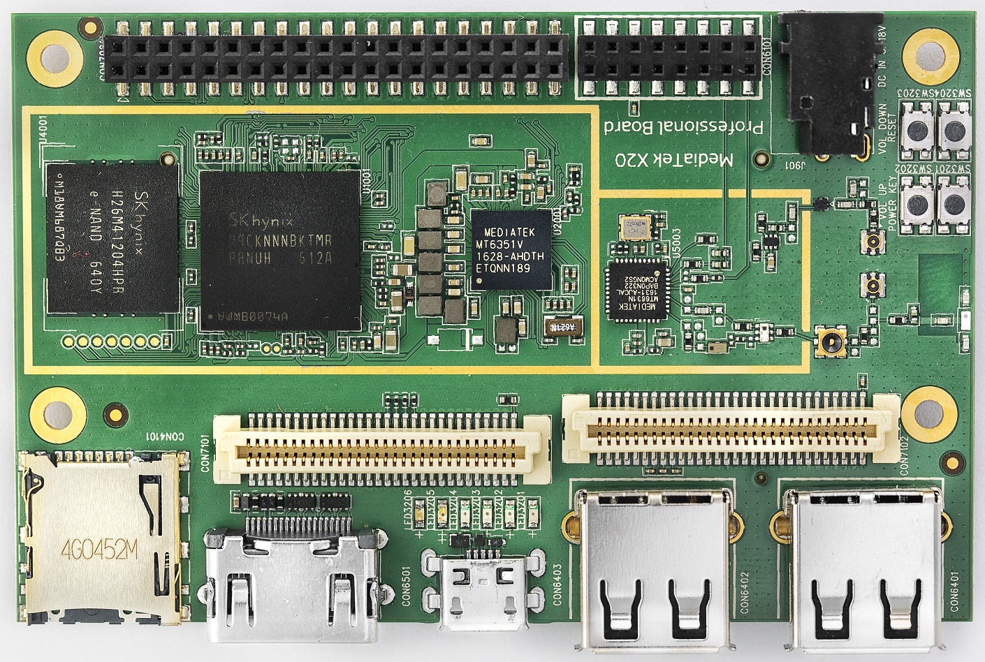
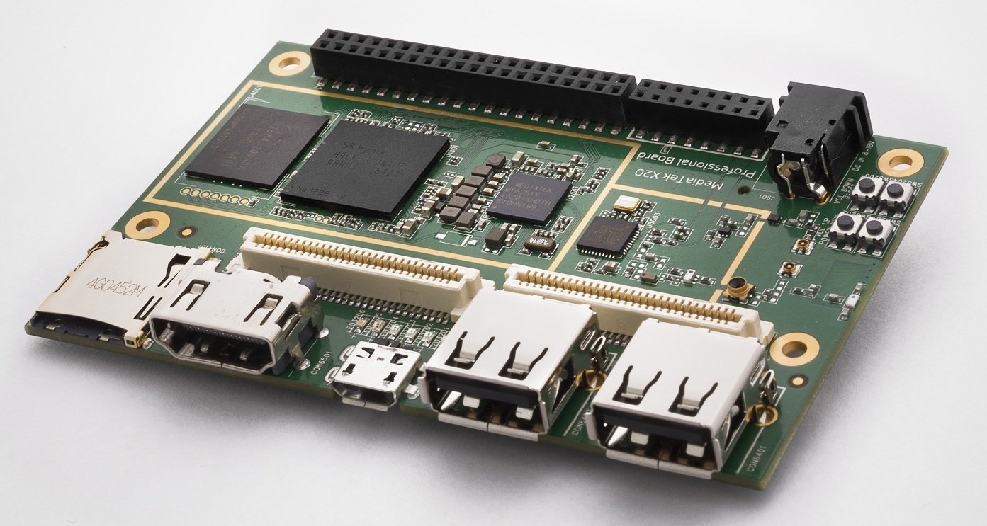
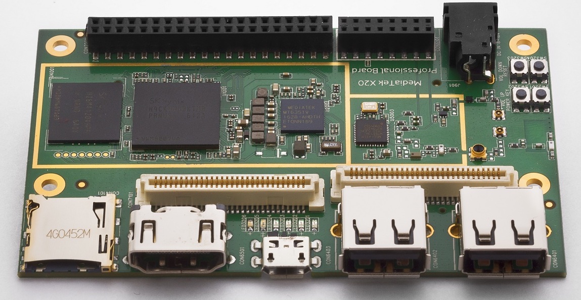
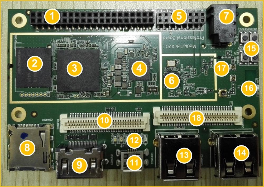
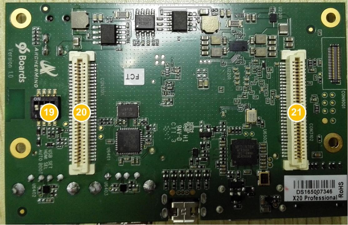
Board Overview
| Position | Reference | Description |
|---|---|---|
| 1 | CON7001 | Low Speed Expansion Connector |
| 2 | U4001 | 8GB EMMC |
| 3 | U1001 | MediaTek X20 SoC MT6797 + 2GB LPDDR3 |
| 4 | U2001 | PMIC MT6351 |
| 5 | CON6101 | Analog Expansion Connector |
| 6 | U5003 | WLAN/Bluetooth/GPS |
| 7 | J901 | DC Power Outlet |
| 8 | CON4101 | Micro SD Card Socket |
| 9 | CON6501 | HDMI Type A Port |
| 10 | CON7101 | High Speed Connector |
| 11 | CON6403 | Micro USB Type B Connector |
| 12 | LED3201-LED3206 | LED3205 is WLAN LED3206 is BT LED3291-3204 is user defined |
| 13 | CON6402 | USB Host2 Connector |
| 14 | CON6401 | USB Host1 Connector |
| 15 | SW3201-SW3204 | SW3202 is Vol up SW3203 is Vol Down SW3201 is Power SW3204 is Reset |
| 16 | ANT5001 | Bluetooth/WLAN Antenna |
| 17 | CON5006 | GPS Antenna connector |
| 18 | CON7102 | High Speed Connector 2 |
| 19 | SW3205 | Switch for Auto boot and USB Host set |
| 20 | CON3101 | RF Expansion Connector 1 |
| 21 | CON3102 | RF Expansion Connector 2 |
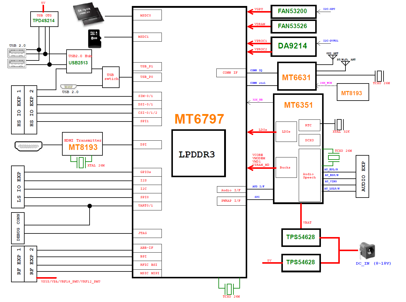
System Block Diagram
Getting Started
Prerequisites
Before you power up your MediaTek X20 Professional Board for the first time you will need the following:
- MediaTek X20 Professional Board
- A 96Boards compliant power supply (sold separately ).
- A HDMI or DVI LCD Monitor that supports a resolution of 1080P/60Hz.
- HDMI-HDMI cable or HDMI-DVI cable to connect the board to the Monitor.
- A computer keyboard with USB interface.
- A computer mouse with USB interface.
Starting the board for the first time
To start the board, follow these simple steps:
- Connect the HDMI cable to the MediaTek X20 Professional Board connector (marked CON6501) and to the LCD Monitor.
- Connect the keyboard to USB connector marked CON6402 and the mouse to the USB connector marked CON6401. (It doesn’t matter which order you connect them in. )
- Plug the power supply into the power outlet.
- Press down the button (marked SW3201), and keep more than 3 seconds, the Android system will start.
Note: If set the first pin (AUTO_BOOT_SET) of switch SW3205 to the position ON, the Android system will start automatically when the power supply is plugged into the power outlet.
Component Details
Processor
MT6797 is a highly integrated application processor which uses an industry-leading Tri-Cluster Deca-Core CPU Architecture.
- Dual-core ARM@Cortex-A72 MPCoreTM operating at up to 2.3GHz
- Quad-core ARM@Cortex-A53 MPCoreTM operating at up to 1.85GHz
- Quad-core ARM@Cortex-A53 MPCoreTM operating at up to 1.4GHz
- Quad-core Mali-T880 operating at up to 700MHz
- DVFS technology with adaptive operating voltage from 0.7V to 1.2V
- EMMC 5.1
- LPDDR-3
- SDIO 2.0/3.0 protocols
- USB 2.0 host/device mode
- Dual SIM/USIM interface
- Two ARM@Cortex-R4 processors with max. 800MHz for modem subsystem
- FDD/TDD up to 300Mbps downlink,50Mbps uplink
- 3G modem support most main features in 3GPP Release 7 and Release 8
- Embody wireless communication device, including WLAN(2.4GHz and 5GHz), Bluetooth® wireless technology and GPS.
- Portrait panel resolution up to WQXGA(2500*1600)
- Integrated image signal processor supports 25MP@30fps
PMIC
There are a PMIC and two dedicated DC - DC converters for MT6797 platform. MT6351 is a power management system chip, containing 8 buck converters and 31 LDOs. it also integrates an high-quality audio CODEC. DA9214 is a 4-phase high efficiency buck converter. It is applied to offer the kernel power of APU. FAN53555 is a high efficiency step-down switching regulator. It is applied to offer the DVDD power of GPU.
Memory (DRAM)
The MediaTek X20 Professional Board provides 2GB LPDDR3-SDRAM which is a 2-channel and 32bit width bus implementation interfacing directly to the MT6797 build-in LPDDR controller. The maximum DDR clock is 933MHz. It is mounted over the MT6797 using pop technology.
Storage
The MediaTek X20 Professional Board provides an 8GB EMMC which is compliant with EMMC 5.1.
Micro SDHC
The MediaTek X20 Professional Board SD slot signals are routed directly to the MT6797 MSDC1 interface. It meets the SD3.0 standard.
Boot ROM
The MediaTek X20 Professional Board boots up from the EMMC.
Networking
WiFi
- Dual-band (2.4/5GHz) single stream 802.11 a/b/g/n/ac RF, 20/40/80MHz bandwidth.
- Integrated 2.4GHz PA with max. 20dBm CCK output power, 5GHz PA OFDM 54Mbps output power 17dBm and VHT80 MCS9 output power 15dBm.
- Typical Rx sensitivity :-76.5dBm at both 11g 54Mbps mode and 11a 54Mbps mode,-62dBm at 11ac VHT80 MCS9 mode
- Integrated power detector to support per packet Tx power control
- On-board BT and WLAN antenna
The MediaTek X20 Professional Board also has a RF connector to connect the external antenna or other RF device. If you want to use this function, you should put the R5072 on with 0ohm resistor and remove the R5071 from the board.
Bluetooth
- Bluetooth® wireless technology specification V2.1+EDR, 3.0+HS and 4.1+HS compliant
- Integrated PA with 8dBm (class 1) transmit power
- Typical Rx sensitivity: GFSK -94dBm, DQPSK -93dBm, 8-DPSK -87.5dBm.
GPS
The GPS implementation is based on MTK connectivity chip MT6631 (U5003) supporting GPS, Galileo, Glonass and Beidou. It can receive GPS, Galileo, Beidou / Glonass simultaneously for more accurate positioning. But there is no GPS antenna on the board. You need to connect an external antenna to the RF connector CON5006.
HDMI
The 96Boards specification calls for an HDMI port to be present on the board. The MT6797 doesn’t include a built-in HDMI interface. The MediaTek X20 Professional Board deploys the built-in DPI interface as the source for the HDMI output. A peripheral Bridge IC (U6502, MT8193) performs this task and it supports a resolution from 480i to 1080p at 30Hz.
MIPI-DSI
The MediaTek X20 Professional Board implements two 4-lane MIPI_DSI interfaces. It can support up to WQXGA(2560x1600 @60fps). The MediaTek X20 Professional Board routes the MIPI_DSI interface signals to the DSI-0 and DSI-1 interfaces of the Soc MT6797.Both DSI-0 and DSI-1 are 4 data lane(Up to 1.2Gbps/lane) interface. For external interfaces,DSI-0 is on the High Speed Expansion connector CON7101 and DSI-1 is on the High Speed Expansion connector CON7102.
Camera Interface
The MediaTek X20 Professional Board supports three camera interfaces, two with a 4-lane MIPI_CSI interface and one with 2-lane MIPI_CSI interface(Up to 2.5Gbps/lane). CSI-0 and CSI-1 are 4-lane interfaces, which can support 25M camera . CSI-2 is a 2-lane interface which can support 8M camera. These are all routed to the Soc MT6797 directly. For external interfaces,CSI-0 and CSI-2 are on the High Speed Expansion connector CON7101 and CSI -1 is on the High Speed Expansion connector CON7102.
Camera capability to support PIP/VIV
| Mode | CSI | Interface | ISP Number | Sensor Resolution |
|---|---|---|---|---|
| Non PIP/VIV | CSI-0 | CSI-0: 4lane/2.5Gbps | ISP0+ISP1 | 25M@30fps |
| CSI-1 | CSI-1: 4lane/2.5Gbps | ISP0+ISP1 | 25M@30fps | |
| CSI-2 | CSI-2: 2lane/2.3Gbps | ISP0 or ISP1 | 8M@30fps | |
| PIP/VIV | CSI-0+ CSI-1 | CSI-0: 4lane/2.5Gbps CSI-1: 4lane/2.5Gbps | CSI-0: ISP0 CSI-1: ISP1 | 13M@30fps 13M@30fps |
| CSI-0+ CSI-2 | CSI-0: 4lane/2.5Gbps CSI-2: 2lane/2.3Gbps | CSI-0: ISP0 CSI-2: ISP1 | 13M@30fps 8M@30fps | |
| CSI-1+ CSI-2 | CSI-1: 4lane/2.5Gbps CSI-2: 2lane/2.3Gbps | CSI-1: ISP0 CSI-2: ISP1 | 13M@30fps 8M@30fps |
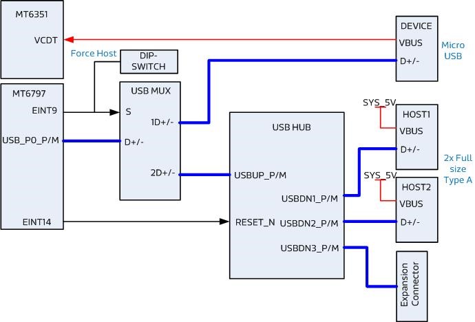
USB Ports
The MediaTek X20 Professional Board supports a USB device port and three USB host ports via a USB MUX(U6503). The input channel( D+/D-) of USB MUX is connected to the P0 port of the Soc MT6797, and the two output channels(1D+/1D-,2D+/2D-) are connected to micro USB port and USB hub respectively. The three USB host ports are connected to the downstream ports of the USB hub. The control of U6503 is done via a software controlled GPIO (USB_SW_SEL, EINT9 from the Soc MT6797). When this signal is logic low, ‘0’, the USB data lines are routed to the Micro USB connector and the MT6797 P0 port is set to device mode. When ‘USB_SW_SEL’ is logic level high, ‘1’, the USB data lines are routed to U6401 (a 3-port USB HUB) and the MT6797 P0 port is set to host mode. The user can overwrite the software control by sliding the switch 3 of the dip-switch SW3205 to the ‘ON’ position. That action forces the USB–MUX (U6503) to route the USB data lines to the USB HUB. The overwrite option exists for the host mode only, you cannot hardware overwrite the MUX to force device mode. If the switch 1 and 3 of the dip-switch SW3205 are both on the ‘OFF’ position, the software is set to the HOST mode by default. But, when a device is plugged into the MICRO USB port CON6403 (Voltage 5V is detected on VBUS by MT6351), the software is automatically switched to the device mode and the MUX(U6503) is switched to micro USB port. When the device is removed(There is no voltage detected on VBUS by MT6351), it is returned to the HOST mode and the MUX(U6503) is switched to USB hub, then the three host ports are available. If the switch 1 of the dip-switch SW3205 is on the ‘ON’ position and the switch 3 of the dip-switch SW3205 is on the ‘OFF’ position, the software is set to device mode. At this time, if you want to use the host mode, you need to force the switch 3 of the dip-switch SW3205 to the ‘ON’ position.
USB Host ports
The MediaTek X20 Professional Board supports three USB host port via a USB2.0 hub (U6401 USB2513-AEZG).
- Port 1 of the USB HUB is routed to CON6401, a Type A USB Host connector. A current limited controller (U6402) sets the Power Current limit to 1.18A.
- Port 2 of the USB HUB is routed to CON6402, a Type A USB Host connector. A current limited controller (U6403) sets the Power Current limit to 1.18A.
- Port 3 of the USB HUB is routed to the High Speed Expansion connector. No current limited controller is implemented on the board for this channel.
USB Device ports
The MediaTek X20 Professional Board implements a device port. The port is located at CON6403, a Micro USB type B.
Note: the board can work in one mode at a time, Host mode or Device mode, not both.
Audio
The MediaTek X20 Professional Board has four audio ports: BT, HDMI, PCM and analog port. The analog port which connected to MT6351 includes a stereo handset IO and two analog audio outputs. The internal audio CODEC block diagrams of MT6351 are listed below.
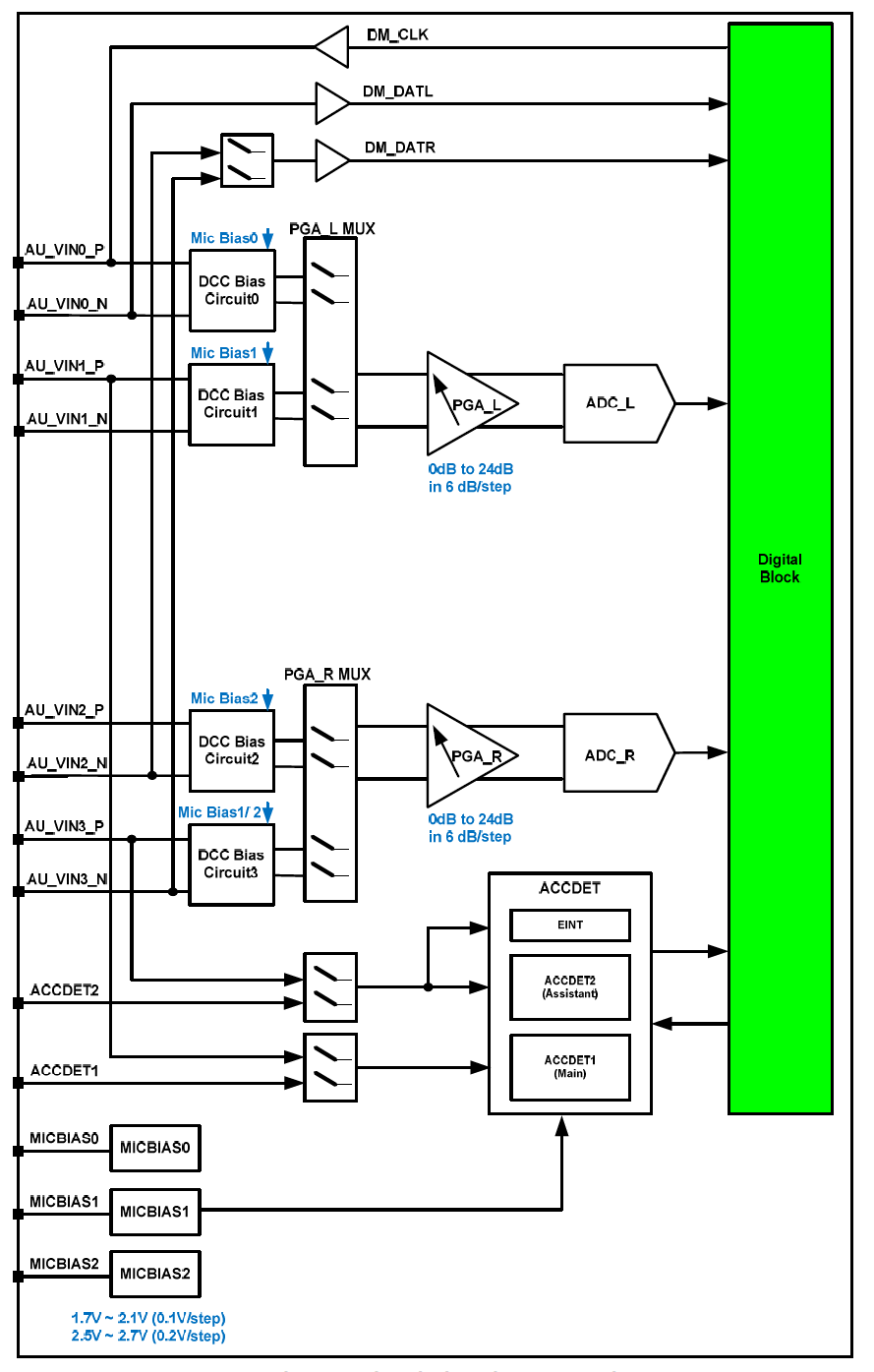
Audio/Speech uplink and accessory detection
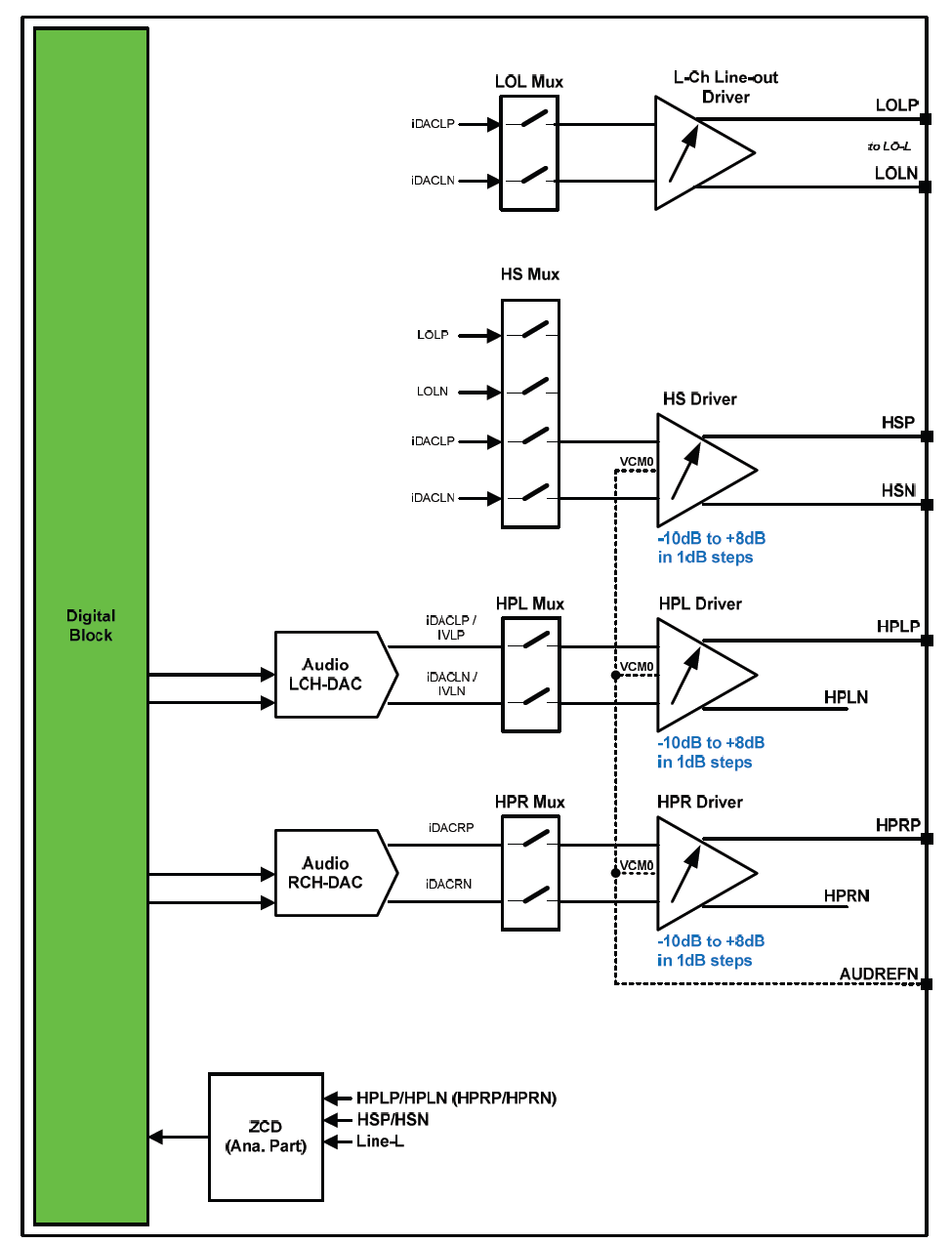
Audio/Speech downlink and headphone detection
DC Power
The MediaTek X20 Professional Board can be powered by two ways:
- 8V to 18V supply from a dedicated DC jack(J901)
- 8V to 18V supply from the DC_IN pins on the Low Speed Expansion Connector(CON7001)
Power Measurement
The MediaTek X20 Professional Board has two current sense resistors R923, R926.
| Reference | Net | Description |
|---|---|---|
| R923 | SYS_5V | To measure the current of SYS_5V power |
| R926 | VBAT | To measure the current of VBAT power |
External Fan Connection
The 96Boards specification calls for supporting an external fan. That can be achieved by using the 5V or the SYS_DCIN (12V), both present on the Low Speed Expansion connector.
UART
The MediaTek X20 Professional Board has two UART ports (UART1 / UART0), both present on the Low Speed Expansion connector. They are routed to the UART1 and UART0 interface of MT6797 separately.
Buttons
The MediaTek X20 Professional Board presents four buttons. They are Power key, VOL up key, VOL down key and Reset key. The power ON/OFF and RESET signals are also routed to the Low Speed Expansion connector.
Power Button
The push-button SW3201 serves as the power-on/sleep button. Upon applying power to the board, press the power button for more than 3 seconds, the board will boot up. Once the board is running you can turn power-off by pressing the power button for more than 3 seconds. If the board is in a sleep mode, pressing the power bottom will wake up the board. Oppositely, if the board is in an active mode, pressing the power bottom will change the board into sleep mode.
Reset Button
The push-button SW3204 serves as the hardware reset button. press the button for more than 1 seconds, the system will be rebooted.
Volume up
The Volume UP button is used to control the output speaker volume of the MediaTek X20 Professional Board.
Volume down
The Volume Down button is used to control the output speaker volume of the MediaTek X20 Professional Board.
Dip-switch
There is a four-channel dip-switch(SW3205) on the board.
- Channel 1:”AUTO BOOT” used to boot the board automatically. If set the switch on , the system will start automatically when the power supply is plugged into the power outlet.
- Channel 2:NC.
- Channel 3:”USB SET”, the user can overwrite the software control by sliding the switch to the ‘ON’ position. The overwrite option exists for the host mode only, you cannot hardware overwrite the MUX to force device mode.
- Channel 4: NC
LED Indicators
The MediaTek X20 Professional Board has six LEDs.
Two activity LEDs
- WiFi activity LED –The MediaTek X20 Professional Board drives this Yellow LED via GPIO136, an IO from MT6797.
- BT activity LED –The MediaTek X20 Professional Board drives this Blue LED via GPIO137, an IO from MT6797.
Four User LEDs
The four user LEDs are surface mount Green in 0603 size located next to the micro USB connector. The MediaTek X20 Professional Board drives the four LEDs from the MT6797 GPIO: GPIO138, GPIO139, GPIO140, GPIO135.
Additional Functionality
The MediaTek X20 Professional Board also has a additional interface (CON9001)for user debugging. It includes JTAG , UART0 and UART1 interface. The position is reserved, but the component is not mounted in the mass production. The component of CON9001 is AXT640124 produced by Panasonic. This interface should be used with the MTK debug board .
Expansion Connectors
Low Speed Expansion Connector
The following tables show the Low Speed Expansion Connector pin out:
| MediaTek X20 Signals | 96Boards Signals | PIN | PIN | 96Boards Signals | MediaTek X20 Signals |
|---|---|---|---|---|---|
| GND | GND | 1 | 2 | GND | GND |
| UCTS0 | UART0_CTS | 3 | 4 | PWR_BTN_N | PWRKEY |
| UTXD0 | UART0_TxD | 5 | 6 | RST_BTN_N | SYSRSTB |
| URXD0 | UART0_RxD | 7 | 8 | SPI0_SCLK | SPI0_CK |
| URTS0 | UART0_RTS | 9 | 10 | SPI0_DIN | SPI0_MI |
| UTXD1 | UART1_TxD | 11 | 12 | SPI0_CS | SPI0_CS |
| URXD1 | UART1_RxD | 13 | 14 | SPI0_DOUT | SPI0_MO |
| SCL4 | I2C0_SCL | 15 | 16 | PCM_FS | PCM0_SYNC |
| SDA4 | I2C0_SDA | 17 | 18 | PCM_CLK | PCM0_CLK |
| SCL5 | I2C1_SCL | 19 | 20 | PCM_DO | PCM0_DO |
| SDA5 | I2C1_SDA | 21 | 22 | PCM_DI | PCM0_DI |
| EINT16 | GPIO-A | 23 | 24 | GPIO-B | EINT5 |
| EINT4 | GPIO-C | 25 | 26 | GPIO-D | EINT3 |
| EINT2 | GPIO-E | 27 | 28 | GPIO-F | EINT1 |
| DSI_TE | GPIO-G | 29 | 30 | GPIO-H | LCM_RST |
| CAM_RST0 | GPIO-I | 31 | 32 | GPIO-J | CAM_PDN0 |
| CAM_RST2 | GPIO-K | 33 | 34 | GPIO-L | CAM_PDN1 |
| VIO18_PMU | +1V8 | 35 | 36 | SYS_DCIN | DC_IN |
| SYS_5V | +5V | 37 | 38 | SYC_DCIN | DC_IN |
| GND | GND | 39 | 40 | GND | GND |
UART {0/1}
The 96Boards specifications calls for a 4-wire UART implementation, UART0 and an optimal second 2-wire UART, UART1 on the Low Speed Expansion Connector.
- The MediaTek X20 Professional Board implements UART0 as a 4-wire UART that connects directly to the Soc MT6797. These signals are driven at 1.8V.
- The MediaTek X20 Professional Board implements UART1 as a 2-wire UART that connects directly to the Soc MT6797. These signals are driven at 1.8V.
I2C {0/1}
The 96Boards specification calls for two I2C interfaces to be implemented on the Low Speed Expansion Connector.
The MediaTek X20 Professional Board implements both interfaces named I2C4 and I2C5. They connect directly to the Soc MT6797. Each of the I2C lines is pulled up to VIO18_PMU via 4.7K resistor.
GPIO {A-L}
The 96Boards specification calls for 12 GPIO lines to be implemented on the Low Speed Expansion Connector. Some of these GPIOs may support alternate functions for DSI/CSI control
The MediaTek X20 Professional Board implements this requirement. All GPIOs are routed to the Soc MT6797.
- GPIO A -Connects to EINT16 of Soc MT6797, can serves as external interrupt supporting the 96Boards requirements to create a wake-up event for the Soc. It is a 1.8V signal.
- GPIO B -Connects to EINT5 of Soc MT6797, can serves as external interrupt supporting the 96Boards requirements to create a wake-up event for the Soc. It is a 1.8V signal.
- GPIO C -Connects to EINT4 of Soc MT6797, can serves as external interrupt supporting the 96Boards requirements to create a wake-up event for the Soc. It is a 1.8V signal.
- GPIO D -Connects to EINT3 of Soc MT6797, can serves as external interrupt supporting the 96Boards requirements to create a wake-up event for the Soc. It is a 1.8V signal.
- GPIO E -Connects to EINT2 of Soc MT6797, can serves as external interrupt supporting the 96Boards requirements to create a wake-up event for the Soc. It is a 1.8V signal.
- GPIO F -Connects to EINT1 of Soc MT6797, can serves as external interrupt supporting the 96Boards requirements to create a wake-up event for the Soc. It is a 1.8V signal.
- GPIO G -Connects to DSI_TE of Soc MT6797, can serves as DSI_TE or GPIO179. It is a 1.8V signal.
- GPIO H -Connects to LCM_RST of Soc MT6797, can serves as LCM_RST or GPIO180. It is a 1.8V signal.
- GPIO I -Connects to CAM_RST0 of Soc MT6797, can serves as CAM_RST0 or GPIO32. It is a 1.8V signal.
- GPIO J -Connects to CAM_PDN0 of Soc MT6797, can serves as CAM_PDN0 or GPIO28. It is a 1.8V signal.
- GPIO K -Connects to CAM_RST2 of Soc MT6797, can serves as CAM_RST2 or GPIO35. It is a 1.8V signal.
- GPIO L -Connects to CAM_PDN2 of Soc MT6797, can serves as CAM_PDN2 or GPIO34. It is a 1.8V signal.
SPI 0
The 96Boards specification calls for one SPI bus master to be provided on the Low Speed Expansion Connector.
The MediaTek X20 Professional Board implements a full SPI master with 4 wires, CLK, CS, MOSI and MISO. The signals are connected directly to the Soc MT6797 and driven at 1.8V.
PCM/I2S
The 96Boards specification calls for one PCM/I2S bus to be provided on the Low Speed Expansion Connector. The CLK, FS and DO signals are required while the DI is optional.
The MediaTek X20 Professional Board implements a PCM/I2S interface with 4 wires, CLK, FS, DO and DI. The signals are connected directly to the Soc MT6797 and driven at 1.8V.
Power and Reset
The 96Boards specification calls for a signal on the Low Speed Expansion Connector that can power on/off the board and a signal that serves as a board reset signal. The MediaTek X20 Professional Board routes the PWR_BTN_N (named PWRKEY on schematic) signal to the PWRKEY pin of the PMIC MT6351. This signal is driven by SW3201 as well, the on-board power on push-button switch. A mezzanine implementation of this signals should not drive it with any voltage, the only allowed operation is to force it to GND to start the board from a sleep mode. The MediaTek X20 Professional Board routes the RST_BTN_N (named SYSRSTB on schematic) signal to the SYSRSTB pin of the PMIC MT6351.
Power Supplies
The 96Boards specification calls for three power rails to be present on the Low Speed Expansion Connector:
- +1.8V Max of 100mA
- +5V Provide a minimum of 5W of power (1A).
- SYS_DCIN 8V-18V input with enough current to support all the board functions or the output DCIN from on-board DC Connector able to provide a minimum of 7W of power.
The MediaTek X20 Professional Board supports these requirements as follows:
- +1.8V Driven by PMIC MT6351 up to 1000mA. It is the system IO power (VIO18_PMU), and it can supply power up to 200mA to the Low Speed Expansion Connector.
- +5V Driven by a 6A DC-DC buck converter (U901). It also provides the VBUS power to the two USB host connectors (CON6401, CON6402) and the HDMI 5V power to the HDMI connector (CON6501).The remaining capacity provides a max current of 2A to the Low Speed Expansion Connector, for a total of 10W which meets the 96Boards requirements.
- SYS_DCIN Can serves as the board’s main power source or can receive power from the board. The voltage range is from 8V to 18V.
High Speed Expansion Connector
CON7101
| MediaTek X20 Signals | 96Boards Signals | PIN | PIN | 96Boards Signals | MediaTek X20 Signals |
|---|---|---|---|---|---|
| SPI1_MO | SD_DAT0/SPI1_DOUT | 1 | 2 | CSI0_C+ | RCP |
| NC | SD_DAT1 | 3 | 4 | CSI0_C- | RCN |
| NC | SD_DAT2 | 5 | 6 | GND | GND |
| SPI1_CS | SD_DAT3/SPI1_CS | 7 | 8 | CSI0_D0+ | RDP0 |
| SPI1_CK | SD_SCLK/SPI1_SCLK | 9 | 10 | CSI0_D0- | RDN0 |
| SPI1_MI | SD_CMD/SPI1_DIN | 11 | 12 | GND | GND |
| GND | GND | 13 | 14 | CSI0_D1+ | RDP1 |
| CAM_CLK0 | CLK0/CSI0_MCLK | 15 | 16 | CCSI0_D1- | RDN1 |
| CAM_CLK1 | CLK1/CSI1_MCLK | 17 | 18 | GND | GND |
| GND | GND | 19 | 20 | CSI0_D2+ | RDP2 |
| TCP | DSI_CLK+ | 21 | 22 | CSI0_D2- | RDN2 |
| TCN | DSI_CLK- | 23 | 24 | GND | GND |
| GND | GND | 25 | 26 | CSI0_D3+ | RDP3 |
| TDP0 | DSI_D0+ | 27 | 28 | CSI0_D3- | RDN3 |
| TDN0 | DSI_D0- | 29 | 30 | GND | GND |
| GND | GND | 31 | 32 | I2C2_SCL | SCL2 |
| TDP1 | DSI_D1+ | 33 | 34 | I2C2_SCL | SDA2 |
| TDN1 | DSI_D1- | 35 | 36 | I2C3_SDA | SCL3 |
| GND | GND | 37 | 38 | I2C3_SDA | SDA3 |
| TDP2 | DSI_D2+ | 39 | 40 | GND | GND |
| TDN2 | DSI_D2- | 41 | 42 | CSI1_D0+ | RDP0_B |
| GND | GND | 43 | 44 | CSI1_D0- | RDN0_B |
| TDP3 | DSI_D3+ | 45 | 46 | GND | GND |
| TDN3 | DSI_D3- | 47 | 48 | CSI1_D1+ | RDP1_B |
| GND | GND | 49 | 50 | CSI1_D1- | RDN1_B |
| USB_DP_P1_EXP | USB_D+ | 51 | 52 | GND | GND |
| USB_DM_P1_EXP | USB_D- | 53 | 54 | CSI1_C+ | RCP_B |
| GND | GND | 55 | 56 | CSI1_C- | RCN_B |
| NC | HSIC_STR | 57 | 58 | GND | GND |
| NC | HSIC_DATA | 59 | 60 | RESERVED | Pull-up to VIO18_PMU via 100K resistor |
CON7102
| MediaTek X20 Signals | 96Boards Signals | PIN | PIN | 96Boards Signals | MediaTek X20 Signals |
|---|---|---|---|---|---|
| VSIM1_PMU | SD_DAT0/SPI1_DOUT | 1 | 2 | CSI0_C+ | GND |
| SIM1_SCLK | SD_DAT1 | 3 | 4 | CSI0_C- | RCP_A |
| SIM1_SIO | SD_DAT2 | 5 | 6 | GND | RCN_A |
| SIM1_SREST | SD_DAT3/SPI1_CS | 7 | 8 | CSI0_D0+ | GND |
| INT_SIM1 | SD_SCLK/SPI1_SCLK | 9 | 10 | CSI0_D0- | RDP0_A |
| GND | SD_CMD/SPI1_DIN | 11 | 12 | GND | RDN0_A |
| AUX_IN0 | GND | 13 | 14 | CSI0_D1+ | GND |
| AUX_IN1 | CLK0/CSI0_MCLK | 15 | 16 | CCSI0_D1- | RDP1_A |
| AUX_IN2 | CLK1/CSI1_MCLK | 17 | 18 | GND | RDN1_A |
| EINT11 | GND | 19 | 20 | CSI0_D2+ | GND |
| EINT10 | DSI_CLK+ | 21 | 22 | CSI0_D2- | RDP2_A |
| LCM_RST | DSI_CLK- | 23 | 24 | GND | RDN2_A |
| DSI_TE | GND | 25 | 26 | CSI0_D3+ | GND |
| DISP_PWM | DSI_D0+ | 27 | 28 | CSI0_D3- | RDP3_A |
| GND | DSI_D0- | 29 | 30 | GND | RDN3_A |
| TCP_A | GND | 31 | 32 | I2C2_SCL | GND |
| TCN_A | DSI_D1+ | 33 | 34 | I2C2_SCL | CAM_CLK1 |
| GND | DSI_D1- | 35 | 36 | I2C3_SDA | GND |
| TDP0_A | GND | 37 | 38 | I2C3_SDA | CAM_RST0 |
| TDN0_A | DSI_D2+ | 39 | 40 | GND | CAM_PDN0 |
| GND | DSI_D2- | 41 | 42 | CSI1_D0+ | CAM_RST1 |
| TDP1_A | GND | 43 | 44 | CSI1_D0- | CAM_PDN1 |
| TDN1_A | DSI_D3+ | 45 | 46 | GND | CAM_RST2 |
| GND | DSI_D3- | 47 | 48 | CSI1_D1+ | CAM_PDN2 |
| TDP2_A | GND | 49 | 50 | CSI1_D1- | GND |
| TDN2_A | USB_D+ | 51 | 52 | GND | SIM2_SCLK |
| GND | USB_D- | 53 | 54 | CSI1_C+ | SIM2_SIO |
| TDP3_A | GND | 55 | 56 | CSI1_C- | SIM2_SREST |
| TDN3_A | HSIC_STR | 57 | 58 | GND | INT_SIM2 |
| GND | HSIC_DATA | 59 | 60 | RESERVED | VSIM2_PMU |
MIPI CSI {0/1}
The MediaTek X20 Professional Board implementation supports two full 4-lane (1.2Gbps/lane) MIPI-DSI interfaces.DSI-0 is routed to the High Speed Expansion Connector CON7101. DSI-1 is routed to the High Speed Expansion Connector CON7102. These can support a 2k LCM or two 1080P LCMs separately
MIPI CSI {0/1/2}
The 96Boards specification calls for two MIPI-CSI interfaces to be present on the High Speed Expansion Connector. Both interfaces are optional. CSI0 interface can be up to four lanes while CSI1 is up to two lanes. The MediaTek X20 Professional Board implementation supports two 4-lane MIPI-CSI interfaces (CSI-0 and CSI-1)and one 2-lane MIPI-CSI interface(CSI-2). All MIPI-CSI signals are routed directly to/from the Soc MT6797. CSI-0 and CSI-1can support up to 25M@30fps and CSI2 can support up to 8M@30fps. The max data rate of each lane is 2.5Gbps. The three CSI interfaces can work separately in Non PIP/VIV mode. It can also support PIP/VIV mode if two CSI interfaces work together .
I2C {2/3}
The 96Boards specification calls for two I2C interfaces to be present on the High Speed Expansion Connector. Both interfaces are optional unless a MIPI-CSI interface has been implemented. Then an I2C interface shall be implemented. The MediaTek X20 Professional Board implementation supports three MIPI-CSI interfaces and two I2C interfaces. By default, I2C2 is used for CSI-0, I2C3 is used for CSI-1 and CSI-2. Each of the I2C lines is pulled up to VIO18_PMU via a1.5K resistor.
SD/SPI
The 96Boards specification calls for an SD interface or a SPI port to be part of the High Speed Expansion Connector. The MediaTek X20 Professional Board implements a full SPI master with 4 wires (96Boards SPI Configuration), CLK, CS, MOSI and MISO. All the signals are connected directly to the Soc MT6797. These signals are driven at 1.8V.
Clocks
The 96Boards specification calls for one or two programmable clock interfaces to be provided on the High Speed Expansion Connector. These clocks may have a secondary function of being CSI0_MCLK and CSI1_MCLK. If these clocks can’t be supported by the Soc than an alternative GPIO or No-Connect is allowed by the specifications. The MediaTek X20 Professional Board implements three CSI clocks which are connected directly to the Soc MT6797. These signals are driven at 1.8V.
USB
The 96Boards specification calls for a USB Data line interface to be present on the High Speed Expansion Connector. The MediaTek X20 Professional Board implements this requirement by routing USB channel 3 from the USB HUB to the High Speed Expansion Connector.
HSIC
The 96Boards specification calls for an optional MIPI-HSIC interface to be present on the High Speed Expansion Connector. The MediaTek X20 Professional Board implementation doesn’t support this optional requirement.
Reserved
The pin 60 of the High Speed Expansion Connector is pulled up to VIO18_PMU via 100K resistor.
USIM
The MediaTek X20 Professional Board has two USIM interfaces on CON7102.These can support 1.8V and 3V USIM card.
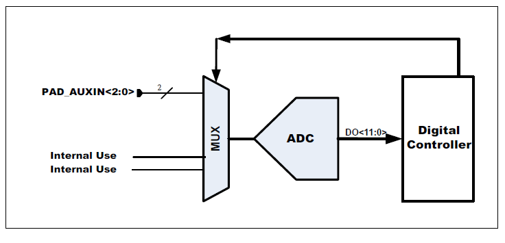
ADC
The MediaTek X20 Professional Board has three ADC inputs on CON7102.All these ADC signals are routed to the ADC MUX of MT6797. The MUX connects with one 12-bit A/D converter which converts the input signal to 12-bit digital data.
GPIO
Beside the 96Boards specification, the MediaTek X20 Professional Board also has 5 GPIOs on CON7102. These are all 1.8V GPIO. For detail application, please refer to the MT6797 GPIO Formal Application Specification.
Analog Expansion Connector
| PIN | MediaTek X20 Signals | Notes |
|---|---|---|
| 1 | AU_LOLP | Positive output of line-out buffer from MT6351 |
| 2 | AU_LOLN | Negative output of line-out buffer from MT6351 |
| 3 | MICBIAS0 | Microphone bias 0 from MT6351 |
| 4 | GND | Ground |
| 5 | AUDREFN | Audio reference ground |
| 6 | MICBIAS1 | Microphone bias 1 from MT6351 |
| 7 | AU_VIN0_P | Microphone channel 0 positive input |
| 8 | AU_HPR | Earphone right channel output |
| 9 | AU_VIN0_N | Microphone channel 0 negative input |
| 10 | AU_HPL | Earphone left channel output |
| 11 | GND | Ground |
| 12 | ACCDET1 | Accessory detection 1 input |
| 13 | FM_ANT | FM antenna positive input |
| 14 | AU_HSP | Headset positive output |
| 15 | FM_RX_N_6631 | FM antenna negative output |
| 16 | AU_HSN | Headset negative output |
Speaker
The speaker signals are routed from the MT6351 built-in Audio CODEC. It should be connected to an external speaker amplifier. Do not connect it to speaker directly. The two signals are:
- AU_LOLP
- AU_LOLN
The main parameters are list in table below.
| Symbol | Parameter | Min. | Typ. | Max. | Unit |
|---|---|---|---|---|---|
| Pout | Maximum output power@<1% THD @PGADL gain=+3dB | 60 | mW | ||
| RLOAD | Output Resistor Load | 600 | Ω | ||
| CLOAD | Output Capacitor Load | 500 | pF | ||
| APGRDL | Analog Programmable Gain Range | -10 | 8 | dB | |
| APGSDL | Analog Programmable Gain Step | 1 | dB |
Mic
The microphone signals are routed to the MT6351 built-in Audio CODEC. It is an uplink input channel and it can be connected to a MIC or a codec line out. The signals are:
- AU_VIN0_P
- AU_VIN0_N
- MICBIAS0(The bias voltage output step size is 0.1V, the range is 1.7~2.1V/2.5~2.7V)
Earphone
The earphone signals are routed from the MT6351 built-in Audio CODEC. It can support stereo earphone directly (Single-ended Output, RLOAD=16/32Ω). The singles are:
- AU_HPL
- AU_HPR
- ACCDET1
- AU_VIN0_P
- AU_VIN0_N
- MICBIAS0
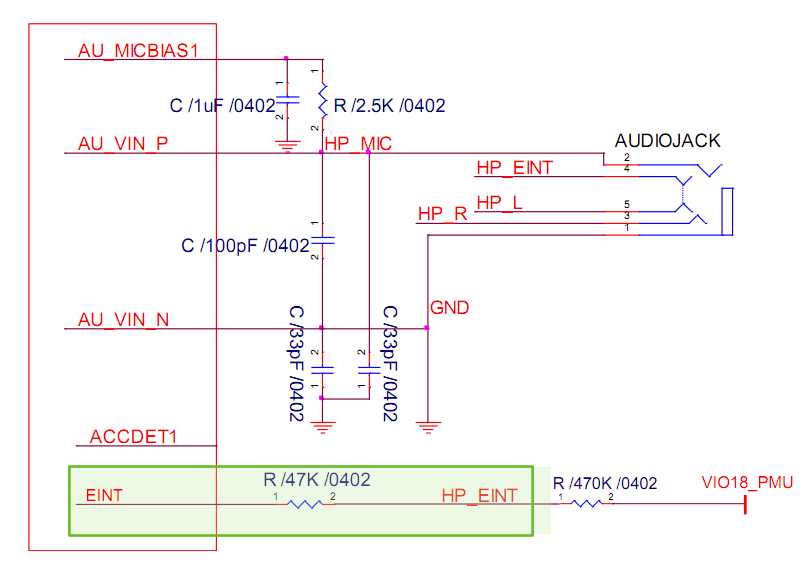
There are two ways (ACC mode and DCC mode ) to detect the accessory. In DCC mode, the ACCDET1 is not use. And the system can detect the earphone inserting via a EINT (External interrupt GPIO of MT6797 ). In ACC mode, the ACCDET1 should be connected to the positive of MIC input signals (between the bypass capacitor and the earphone jack). It is used to detect the Up key, Down Key and Hook key. For the earphone inserting detection, you also need to use an EINT GPIO. The main parameters are list in table below.
| Parameter | Min. | Typ. | Max. | Unit |
|---|---|---|---|---|
| 4-pole Microphone Detection | 2K | 14K | Ω | |
| Microphone impedance detection after 4-pole Microphone plugged-in | ||||
| MICD_LVL[0]: Up key | 400 | 620 | Ω | |
| MICD_LVL[1]: Down key | 150 | 320 | Ω | |
| MICD_LVL[2]:Hook key | 0 | 100 | Ω |
*Load impedance detection range (ACCDET1) by 1&1.5kΩ (1%) MICBIAS resistors.
For earphone application, please refer to the circuit below.
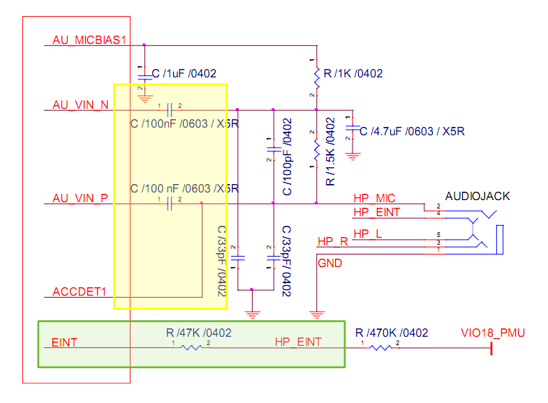
ACC mode schematic diagram
**DCC nide schematic diagram
Headset
The headset signals are routed from the MT6351 built-in Audio CODEC. It can support 16/32Ω receiver directly. The singles are:
- AU_HSP
- AU_HSN
FM Antenna
The FM antenna signals are routed to the MT6631 (U5003), an integrated connectivity device. The two signals below should be kept in differential trace to audio jack.
- FM_ANT
- FM_RX_N_6631
RF Expansion Connector
There are two 60-pin connectors(CON3101 ,CON3102) on the bottom of the board, which are used to connect to the MediaTek X20 RF Board. With it, the MediaTek X20 Professional Board can Support 3/4G communication.
Power Management Overview
Block Diagram
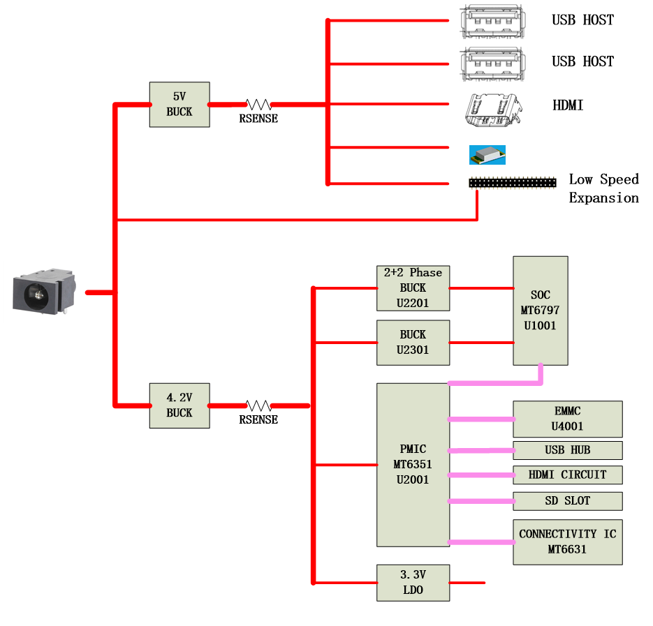
DC Power Input
- An 8V to 18V power from a dedicated DC jack J901.
- An 8V to 18V power from the SYS_DCIN pins on the Low Speed Expansion Connector CON7001.
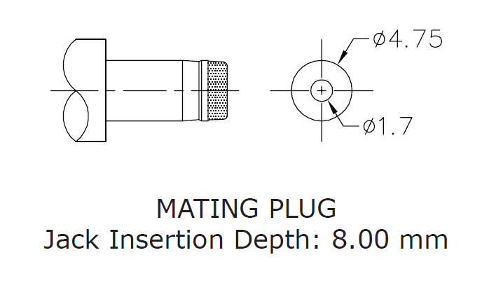
Note: Please refer to the mechanical size of the DC plug below. The inside diameter of the plug is 1.7mm,the outer diameter of the plug is 4.75mm.The positive electrode of the DC plug is in the inside, and the negative pole is outside.
Power Source Selection and Sequencing
The user of the MediaTek X20 Professional Board should never apply power to the board from J901 and the Low Speed Expansion connector at the same time. There is no active or passive mechanism on the MediaTek X20 Professional Board to prioritize one source over the other.
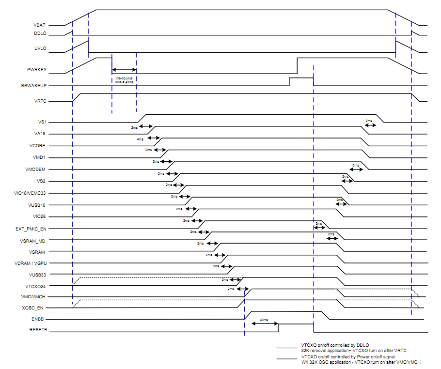
Voltage Rails
| Circuit Type | Net Name | Default ON Voltage(V) | Iout Max (mA) | Expected use |
|---|---|---|---|---|
| BUCK | SYS_5V | 5 | 6000 | system 5V |
| VBAT | 4.2 | 6000 | system power | |
| DVDD_PROC1 | 0.6 ~ 1.3 | 10000 | Core power for Processor of MT6797 | |
| DVDD_PROC2 | 0.6 ~ 1.3 | 10000 | ||
| DVDD_GPU | 0.6 ~ 1.3 | 5000 | Core power for GPU of MT6797 | |
| DVDD_MODEM | 0.9 | 1200 | BB1&AP MCU of MT6797 | |
| VDRAM_PMU | 1 | 3000 | DRAM of MT6797 | |
| DVDD_CORE | 1 | 3000 | core AP Core of MT6797 | |
| DVDD_MDI | 0.9 | 1200 | BB2(LTE) of MT6797 | |
| DVDD_SRAM_MD | 1 | 1200 | MD Memory of MT6797 | |
| VS1_PMU | 2 | 2000 | Low Dropout LDO input | |
| VS2+PMU | 1.4 | 2000 | Low Dropout LDO input | |
| LDO | VTCXO28_PMU | 2.8 | 40 | DAC of MT6797 |
| VTCXO24_PMU | 2.375 | 40 | NOT USE | |
| VSIM1_PMU | 3 | 100 | AVDD_USB_P1 of MT6797 | |
| VSIM2_PMU | 3 | 100 | DVDD28_SIM2 of MT6797 | |
| VCN18_PMU | 1.8 | 200 | connectivity | |
| VCN28_PMU | 2.8 | 40 | connectivity | |
| VCN33_PMU | 3.3 | 500 | connectivity | |
| VDRAM_LDO_PMU | 1.21 | 1200 | NOT USE | |
| VMIPI_PMU | 1.8 | 200 | MT8193 | |
| VUSB33_PMU | 3.07 | 100 | USB power | |
| VUSB10_PMU | 0.9 | 300 | AP Analog module | |
| VIO28_PMU | 2.8 | 200 | TCXO | |
| VIO18_PMU | 1.8 | 1000 | 1.8V IO | |
| VBIF28_PMU | 2.8 | 20 | NOT USE | |
| VEFUSE_PMU | 1.8 | 200 | AP EFUSE | |
| VMC_PMU | 3 | 200 | DVDD of memory card | |
| VMCH_PMU | 3 | 200 | SD card | |
| VEMC_3V3_PMU | 3 | 800 | EMMC | |
| VLDO28_PMU | 2.8 | 800 | MT8193 | |
| VIBR_PMU | 3 | 200 | MT8193 | |
| VGP3_PMU | 1 ~ 1.8 | 300 | NOT USE | |
| VDCXO_PMU | 2.2 | 40 | NOT USE | |
| VA18 | 1.8 | 300 | Audio/ABB | |
| VSRAM_PROC_PMU | 0.6 ~ 1.2 | 250 | CPU1 SRAM power of MT6797 | |
| VRF12_PMU | 1.2 | 145 | MT8193 | |
| VRTC | 2.8 | 2 | RTC | |
| 3V3_LDO | 3.3 | 1000 | HDMI | |
| Other | HDMI_5V | 5 | 700 | HDMI output voltage |
| VBUS_HOST1 | 5 | 1200 | USB host1 output voltage(CON6401) | |
| VBUS_HOST2 | 5 | 1200 | USB host2 output voltage(CON6402) | |
| VIO18_PMU | 1.8 | 200 | 1.8V on LS connector | |
| SYS_5V | 5 | 2000 | 5V on LS connector | |
| DC_IN | 8 ~ 18 | 1000 | 8-18V DCIN on LS connector as output | |
| DC_IN | 8 ~ 18 | 3000 | 8-18V DCIN on LS connector as input |
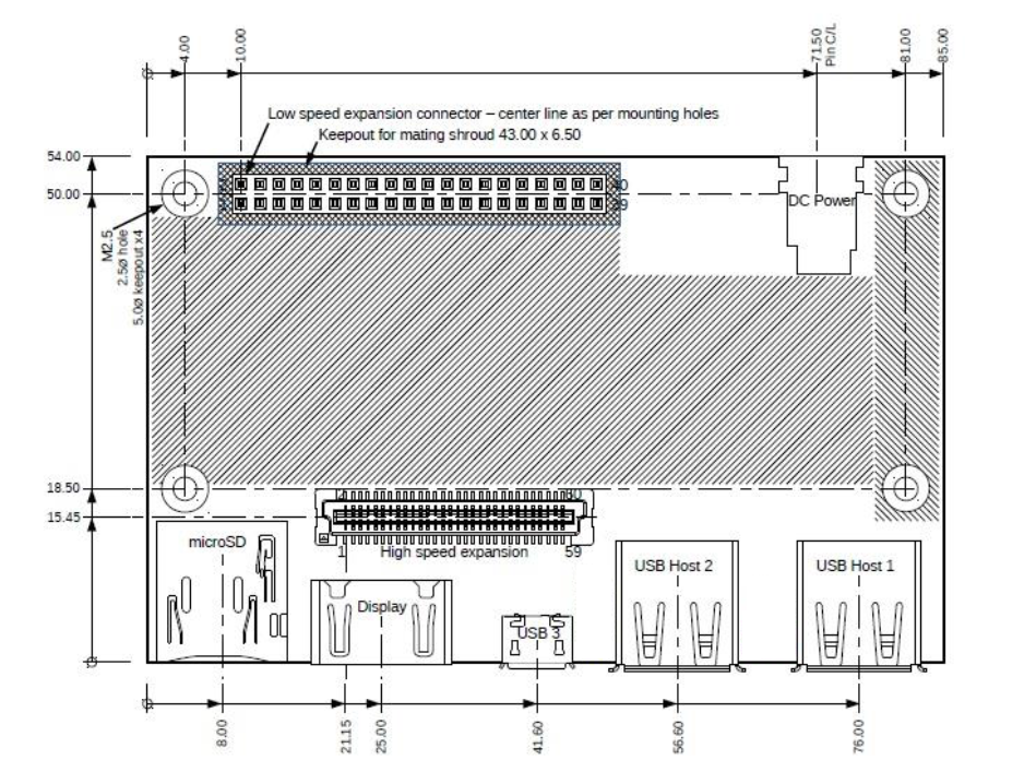
Mechanical Specification
The MediaTek X20 Professional Board is compliant with the 96boards mechanical specification. For the detail size, please see the MediaTek X20 Professional Board 2D Drawing.