Introduction
This guide will walk you through Interfacing with Arduino Shields that use I2C bus.
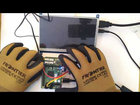
Hardware Setup
- Any 96Boards CE Board
- Shiratech FPGA Mezzanine
- I2C Shield or Sensor
- For the Purpose of this guide I will be using:
Software setup
Running the Demos
- The I2C ports on the Arduino and Raspberry Pie headers act as a pass-through to the I2C0 Pins on the Low Speed Header.
- We first need to enable the i2c pass-through:
sudo i2cset 0 0x6f 0x13 0x00 - This means and device connected over I2C via the FPGA Mezzanine should show up by simply running:
sudo i2cdetect -r 0
MPU6050: C
For the MPU6050, we are going to use one of the example codes from the MRAA repository:
- Fetch the code:
wget https://raw.githubusercontent.com/intel-iot-devkit/mraa/master/examples/c/i2c_mpu6050.c - Compile the code:
gcc i2c_mpu6050.c -o i2c_mpu6050 -lmraa - Run the code:
sudo ./i2c_mpu6050 - After 5 seconds you should see Accelerometer and Gyroscope data show up and refresh every 2 seconds.
I2C 1602 LCD and PCA9685 Servo Controller: Python
For a combined demo of LCD module and PCA9685 Servo controller here is a small python script using the UPM Library:
- Carefully snap the Servo Shield on the Arduino headers of the FPGA mezzanine.
- Connect the I2C LCD to the I2C pins on the Servo Shield
- Connect a 5v Servo on Channel 0.
- Copy the following code and save it as
servo.py
from upm import pyupm_adafruitss as adass
from upm import pyupm_lcm1602 as lcm1602
import time

serv = adass.adafruitss(0,0x40)
lcd = lcm1602.Lcm1602()

lcd.displayOn()
lcd.clear()
lcd.setCursor(0,0)
lcd.write("Hello OpenHours")
lcd.setCursor(1,0)

while True:
    serv.servo(0,1,0)
    lcd.write("Servo Pos: 0  ")
    lcd.setCursor(1,0)
    time.sleep(1)
    serv.servo(0,1,90)
    lcd.write("Servo Pos: 90 ")
    lcd.setCursor(1,0)
    time.sleep(1)
    serv.servo(0,1,160)
    lcd.write("Servo Pos: 160")
    lcd.setCursor(1,0)
    time.sleep(1)
- Run it as
python3 servo.py - The servo should now start moving and the LCD should display the servo’s current position.
Video Demo