- Getting Started
- Out of the Box
- Features
- Starting the board for the first time
- Step 1
- Step 2
- WIFI SDIO : S1,S2,S3 switches
- NPU or CPU UART Debug ports selection: voltage Level shifter enable S3/Bit4 and S5.
- TF Card switches:S6/S7/S8/S9
- High speed expansion SDIO port: S11/S12 switches
- JTAG switches: S10
- 96Boards HS Speed USB2.0: S13
- Display port switches: S14
- Camera CSI switches: S15
- GPIO switches: S16
- Step 3
- Step 4
- Step 5
- Step 6
- What’s Next?
Getting Started
Learn about your TB-96AI board as well as how to prepare and set up for basic use
Setup - What you will need
Need
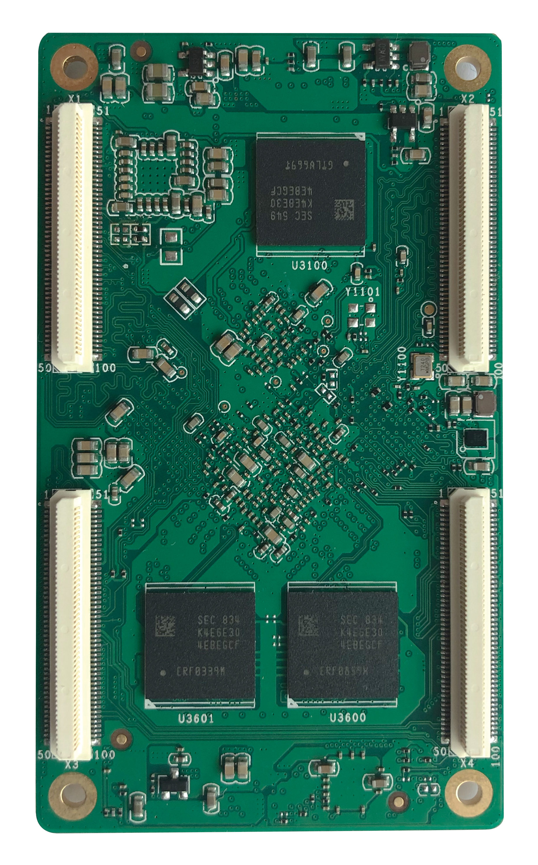
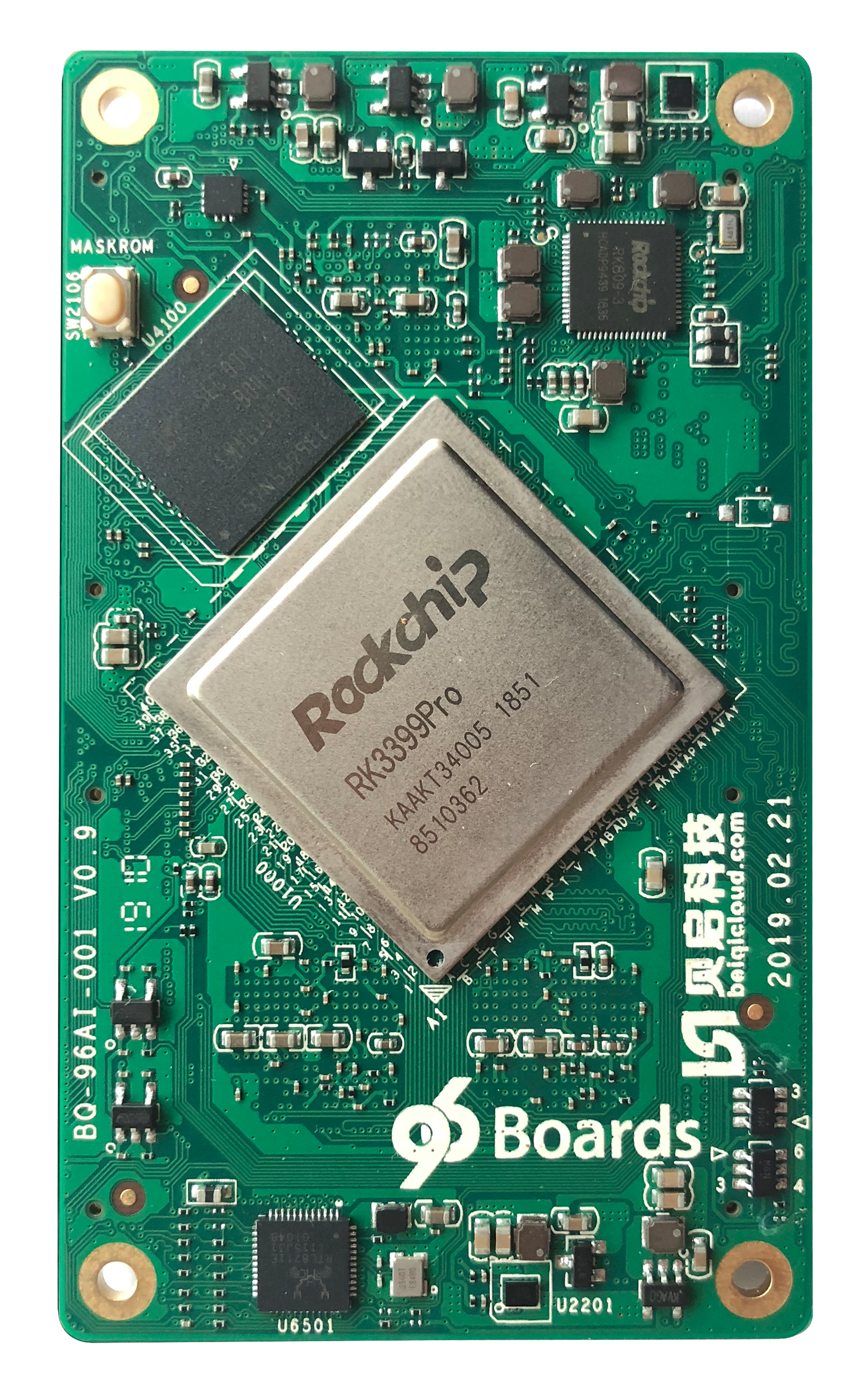
- TB-96AI
- SOM based on the RK3399Pro Application Processor and NPU
- 96Boards SOM Carrier Board
- SOM Baseboard
- Power adapter
- 96Boards specifications requires a 8V-18V with 2000mA Power adapter
- Typc C to Type A Cable
- To connect Baseboard to PC
Out of the Box
The following subsections should describe how to get started with the TB-96AI SoM.
Features
| Component | Description |
|---|---|
| SoC: | Rockchip RK3399Pro with Dedicated NPU |
| CPU: | Dual-core Cortex-A72 up to 1.8GHz Quad-core Cortex-A53 up to 1.4GHz |
| GPU: | ARM® Mali-T860 MP4 Quad-core GPU Supports OpenGL ES1.1/2.0/3.0/3.1, OpenVG1.1, OpenCL, DX11, Support AFBC (frame buffer compression) |
| NPU: | Support 8bit/16bit computing, AI computing power up to 3.0TOPs Full load computing power, low load operation power consumption is low Compatible with Caffe/Mxnet/TensorFlow model, support multi-class framework, support mainstream layer type, easy to add custom layer Provides easy-to-use development tools, PC-based model conversion, performance estimation, and accuracy verification Provides AI application development interface: support Android NN API Provides RKNN cross-platform API, Linux supported TensorFlow development |
| VPU: | Support 4K VP9 and 4K 10bits H265/H264 video decoding, up to 60fps 1080P multi-format video decoding (WMV, MPEG-1/2/4, VP8) 1080P video encoding, support H.264, VP8 format Video post processor: de-interlacing, denoising, edge/detail/color optimization |
| RAM: | Optional configuration with the following options: 3GB LPDRR3(CPU 2GB + NPU 1GB) 8GB LPDDR3(CPU 4GB + NPU 4GB) |
| Storage: | Optional configuration with the following options: 16GB eMMC 32GB eMMC 64GB eMMC 128GB eMMC |
| Connectivity: | Built-in WiFi/BT module, reserved antenna holder, can be directly inserted into the antenna. Built-in Gigabit Ethernet PHY chip, 10/100/1000Mbps adaptive. |
| Camera: | MIPI-CSI×2,Dual camera interface (built-in dual hardware ISP, up to single 13Mpixel or dual 8Mpixel) |
| Display Interface: | Embed two VOPs, support dual-screen simultaneous/dual-screen display, and can choose to output from the following display interface. MIPI-DSI×1 eDP×1 DP×1 HDMI × 1 ( Support 480p/480i/576p/576i/720p/1080p/1080i/4k, support RGB format) |
| Audio Interface: | I2S0: - Support user extended use I2S1: - Speaker×1 - Headphone×1 - MIC×1 I2S2: - HDMI interface audio output - DP interface audio output |
| USB: | Type C: USB3.0/DisplayPort 1.2,OTG USB: USB3.0×1 (according to RK3399Pro design, NPU needs to be mounted on USB3.0, so USB3.0 needs to connect back to NPU, if you need to expand USB3.0 interface, you need external HUB) USB2.0×2, HOST |
| Expansion Interface: | SDMMC(TF Card)×1 SPI×1 UART×3, One of the CPU Debug UARTs, one NPU Debug UART I2C×6 SDIO×1 PCIe×1 PWM×2 GPIO,For detailed GPIO definitions, please refer to the interface definition ADC×3,One for buttons, one for headset microphone detection, and one for user-definable use |
| OS Support: | Android, Linux |
| Mechanical: | 85mm×50mm×1.6mm 96Boards SoM standard dimensions specifications. |
| SoM Connectors | X1 X2 |
Starting the board for the first time
Step 1
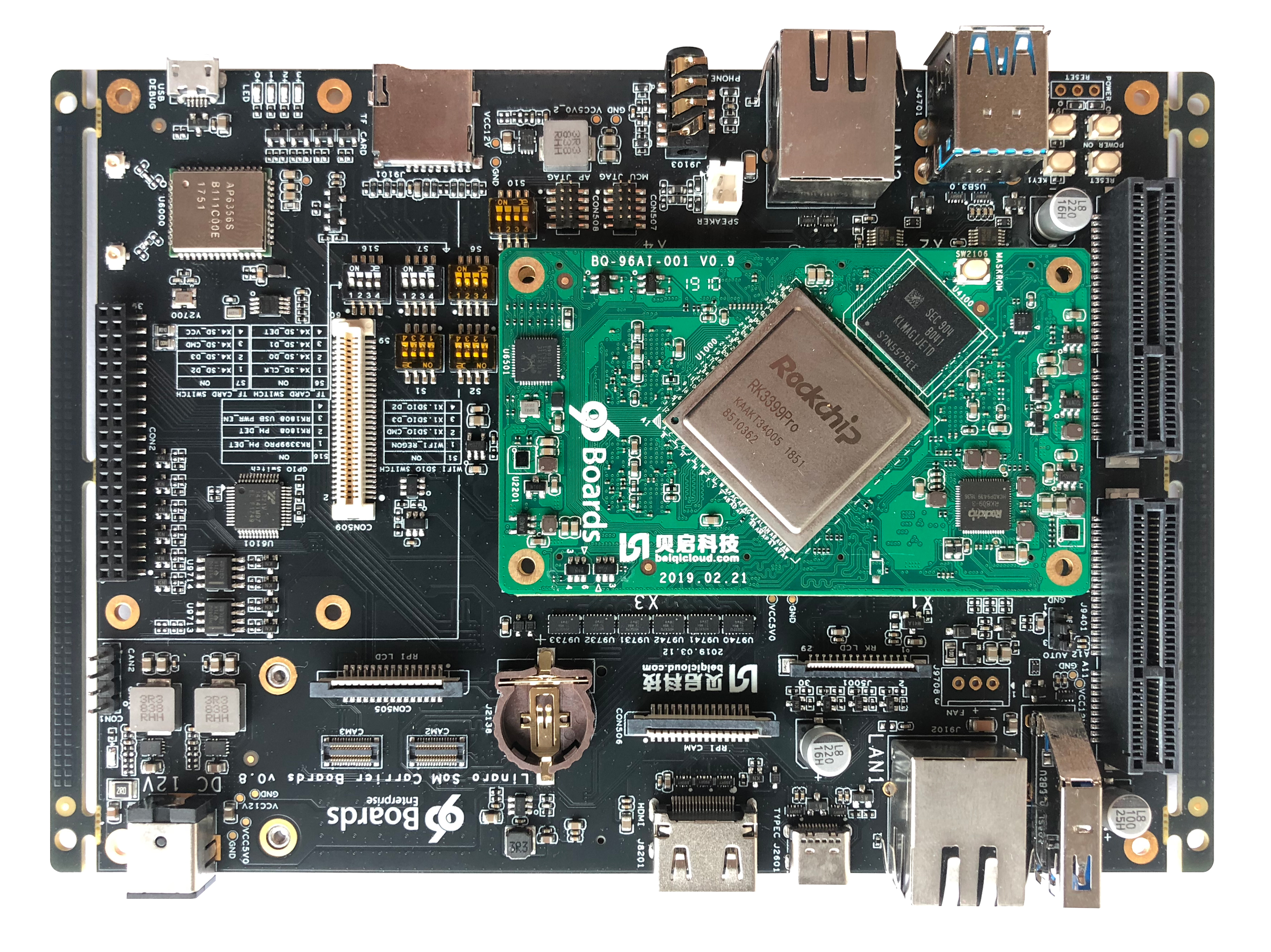
Insert the TB-96AI SoM in the 96Boards Carrier Board as Shown in the figure above.
Step 2
Configure the MUX Switches on the Carrier Board as follows:
WIFI SDIO : S1,S2,S3 switches
For TB-96AI RK3399PRO SOM+Carrier Boards configuration:
- S1,S2 are the used for the SDIO,S1/S2 should be configured to ON.
- The S8,S9,S11,S12 must be configured to OFF,S6 ,S7 must be as on. Bit1/Bit2/Bit3 on S3 are for WIFI,the 3 Bits should be on for WIFI active. S3 Bits functions:
- Bit1: BT wake up CPU
- Bit2: CPU wake up BT
- Bit3: BT enable
- Bit4: UART voltage
NPU or CPU UART Debug ports selection: voltage Level shifter enable S3/Bit4 and S5.
For TB-96AI SoM RK3399Pro UART Debug: Bit4 on S3, S5
- With NPU UART Debug: S3 of Bit4 is ON with 3V3, Bit1/Bit2 of S5 are OFF and the Bit3/Bit4 of S5 are ON.
- With CPU UART Debug: S3 of Bit4 is OFF with 1V8. Bit1/Bit2 of S5 is ON and Bit3/Bit4 of S5 are OFF.
TF Card switches:S6/S7/S8/S9
For TB-96AI RK3399PRO SOM
- S6,S7 are ON and S8,S9,S10 must be OFF for TF Card.
High speed expansion SDIO port: S11/S12 switches
For TB-96AI RK3399PRO SOM
- All Bits of S11 and S12 are ON, and all Bits of S8,S9,S1,S2 are OFF.
- During this case, the WIFI is forbidden to use.
JTAG switches: S10
For TB-96AI RK3399PRO SOM JTAG
- Bit1,Bit2 of S10 are on for MCU JTAG.Bit3,Bit4 of S10 are on for AP JTAG.
- If JTAG is required, all the switches of S6,S7 must be on, All switches on S8,S9 must be OFF. During JTAG the TF card can not work at the same time.
96Boards HS Speed USB2.0: S13
For TB-96AI RK3399PRO SOM
- The USB2.0 of HS speed USB2.0 and MiniPCIe are muxed.
- The Bit1,Bit2,Bit4 on S13 must be OFF.
- If MiniPCIE LTE Module is used, the Bit3 of S13 must be ON. If USB on High speed expansion connector is used,Bit3 of S13 must be OFF.
Display port switches: S14
For TB-96AI RK3399PRO SOM(The J5001 eDP and MIPI DSI on High speed connector can be used at the same time)
- If the eDP display port on RK LCD connector(J5001) is used, the Bit2 of S14 must be OFF.
- If the eDP display port are connect the High speed expansion connector(same DSI pins) is used, the Bit2/Bit3 of S14 must be ON.
- If the MIPI display(DSI) port on High speed expansion connector is used, the Bit1/Bit3 of S14 must be OFF.
Camera CSI switches: S15
For TB-96AI RK3399PRO SOM
The RK3399PRO has two MIPI CSI interface,MIPI_RX0 and MIPI_RX1.
- If the Bit1 of S15 is OFF ,the MIPI_RX0 will be connected to the Raspberry Camera connector(CON506).
- If the Bit1/Bit3 of S15 are ON, the MIPI_RX0 will be connected to the high speed expansion connector(CON509).
- If the Bit4 of S15 is OFF, the MIPI_RX1 will be connected to CAM2 camera connector(CON1701).
- If the Bit4 of S15 is ON, the MIPI_RX1 will be connected to high speed expansion connector(CON509).
GPIO switches: S16
For TB-96AI RK3399PRO SOM:
- Bit1:RK3399Pro earphone plugin check
- Bit2:Void
- Bit3:Void
- Bit4: Void
- The Bit1 must be ON.
Step 3
Connect the TYPEC to PC
Step 4
Long press and hold the Maskrom button as shown in the following figure.
Step 5
Insert power supply.
Step 6
Continue to the Installation page.
What’s Next?
If you are already familiar with the TB-96AI board and would like to change out the stock operating system, please proceed to one of the following pages:
- Downloads page: This page lists all Linaro and 3rd party operating systems available for TB-96AI
- Installation page: If you already have the images you need, this page has information on how to install the different operating systems onto your TB-96AI board
- Support
- From bug reports and current issues, to forum access and other useful resources, we want to help you find answers
Back to the TB-96AI documentation home page